Thermal Management with Fans – There's More to Consider Than You Might Think
With the rise of IoT and cloud computing, today’s designs are packing-in more sensors, transistors, and processors per square inch, leading to higher application densities and functionality. However, with these higher densities comes an unwanted byproduct, additional heat. As is often the case, the limiting factor for such designs is not the capabilities of the individual components, but more likely the limitations of the components due to the excess heat. Understanding that electronic components, especially semiconductors, are designed to work within a specific temperature range beyond which their performance is not guaranteed, is important. As is recognizing the common concern that heat generated by the components themselves, including passive devices, can result in elevated operating temperatures, potentially leading to device failure.
Thermal Management Techniques
To ensure the reliability and correct functioning of any system design it is crucial to employ appropriate thermal management techniques. The fundamental processes by which heat can be removed are conduction, convection and radiation:
- Radiation is rarely effective in most systems as it ideally requires “black body” emitting and receiving surfaces with no obstructions between them.
- Conductive cooling is often the simplest solution and can work well in extracting heat from a component through a printed circuit board (PCB), especially where the metal tracks and ground planes are designed with this in mind.
- Convection cooling relies on heat from a component warming the air around it, with the heat being removed as the warm air rises and is replaced by cooler air. Its effectiveness depends on the orientation of the component and how readily air can flow past it.
Typically, convection cooling is paired with conduction to further dissipate heat that has spread into a PCB, or where a heat sink has been used to extract heat from a component like an integrated circuit. This combination of conduction and convection works fine when airflow is unimpeded, but when electronics are placed in an enclosure, it is another ball game!
Consequently, unless an enclosure is extremely well ventilated, natural convective air cooling will not be sufficient to cope with anything more than very low levels of heat dissipation. This then leads us into an analysis of an appropriate forced-air solution to cool the application, including the type, size and performance of the fan(s) required to achieve this. Shop CUI Devices' full range of ac fans and dc fans.
Choosing a Fan
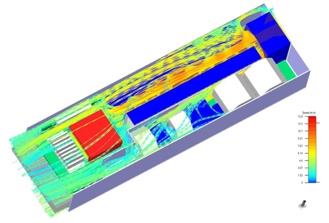
First, it is important to understand where and how much heat is being generated. A thermal profile of the system can be achieved using temperature sensors distributed within the enclosure and on the PCB. It is also necessary to determine the airflow impedance of the system, i.e. the drop in air pressure from inlet to outlet. This can be measured using pressure sensors or by placing the system in an air chamber. Modelling using computational fluid dynamics (CFD), as illustrated below, can also provide an accurate profile.
Once the maximum allowable temperature rise (ΔT) and amount of heat to be dissipated (q) is known, the required airflow (Q) to meet the system’s cooling requirements can be determined by solving a simple equation.
Q = [q/(ρ x Cp x ΔT)] x 60
If we substitute constants for the specific heat of air (Cp) and the density of air (ρ) at a defined temperature (e.g. 26°C), then the equations simplify to:
Q = 0.05 x q/ΔT
for Q in cubic meters per minute (CMM)
Q = 1.76 x q/ΔT
for Q in cubic feet per minute (CFM)
Having calculated the required airflow figure, it is then easy to match this to the specification for a fan, which manufacturers usually provide as a plot of airflow against static pressure. However, static pressure, which is the atmospheric pressure in the enclosure with no airflow, takes no account of the airflow impedance (or back pressure) noted earlier. To address this real-world issue, the back pressure can either be measured for different airflow rates and plotted on the graph such that the intersection provides the required operating point, or the fan could be over-specified to nominally operate at say 50% above the required static pressure airflow, but with a maximum capability that is double the required performance to allow a margin for error.
Of course, if cooling requirements are considered at the outset of a design then precautions can be taken to reduce system impedance and optimize airflow by guiding air towards critical components and ensuring the air inlet and outlet are not obstructed by bulky components. Further fan choice considerations relate to the fan type: with an axial fan, air enters and leaves the fan in the same direction, which is ideal for high airflow in systems with low static pressure; fans where the air is expelled in a different direction have the effect of compressing the air, making such centrifugal-type fans better suited to lower airflow but higher static pressure environments. For more information, read our Axial Fans vs. Centrifugal Fans – What’s the Difference? blog post.
In addition, fan bearing types are also a key consideration when it comes to fan selection with sleeve or ball bearings being the two most common technologies. Sleeve bearings are highly impact resistant and are the more cost-effective of the two options due to their simple design, but have the drawbacks of increased rotational friction, wobble and tilt issues caused by bearing wear, and a generally shorter life expectancy than ball bearings. On the other hand, ball bearings resolve many of the wobble, tilt, and friction issues seen in sleeve bearings. They can also be operated at any angle, unlike sleeve bearings, making them ideal for portable devices. However, ball bearing fans are less impact resistant, noisier, more complex and more expensive than sleeve bearing fans.
A third option addressing the drawbacks of the two bearing types mentioned above, is CUI Devices’ omniCOOL™ system. Found in its line of advanced sleeve bearing fans, the omniCOOL system incorporates either a magnetic structure or enhanced sleeve bearing design to greatly reduce friction, tilt, wobble, and noise. These features work to improve performance and extend operational life, making fans built with the omniCOOL system a cost-effective, higher performance solution compared to traditional fan bearing technologies. For more information, read our Fan Bearing Types – Weighing the Pros and Cons blog post.
Additional Considerations
The selection process does not stop here. A designer also needs to think about issues such as electrical and audible noise, and how they might want to control the fan. Audible noise depends on several factors and is generally dictated by the required airflow. Centrifugal, or blower type, fans are typically noisier than axial fans, while a larger axial fan running at a lower speed will be quieter than a smaller fan that has to run faster to achieve the same airflow. Electromagnetic interference (EMI) is created by a fan’s motor, but with a dc fan this is normally limited to conducted EMI in the power leads, which can usually be suppressed with ferrite beads or shielding.
With densities continually on the rise, the thermal management of your system is likely becoming a top concern. Proper thermal analysis of the system and selection of the appropriate cooling method is vital to prevent critical components from overheating and failing once in operation. In many applications, forced air cooling with a dc fan can be an efficient way to remove the excess heat, but with so many fan configurations and features available, it is essential to understand how fan performance matches your system’s needs.

 Tags:
Tags:
Additional Resources