A Comparison Between Dc Switching Regulators and Linear Regulators
December 8, 2020 by Ron Stull - 9 Minute Read
Electronic systems often require multiple voltages to power the various internal circuits. Non-isolated regulators are a common and easy way to convert one voltage to another. Regulators typically fall into two categories based on the method of conversion: linear or switching. Linear regulators have been around for a long time and are cheap and easy to use. However, the simplicity comes at the cost of low efficiency. Switching regulators on the other hand are more expensive and a little more complex internally but are significantly more efficient and capable of conducting large amounts of current without the same thermal concerns of a linear regulator. In this blog we will investigate why the efficiency is so different between these two regulators and the impact that can have on the end design.
| Linear Regulators | Switching Regulators |
|---|---|
| Simple Design | Complex Design |
| Dissipates Excess Power | Stores Excess Power |
| Lower Efficiency | Higher Efficiency |
| Higher Thermal Stress | Lower Thermal Stress |
Linear Regulators
To explain how the linear regulator works and why it is so inefficient, we will start with an example application (Figure 1). In this case we have a 24 V input that is being converted into a 6 V output with a 1 A load.
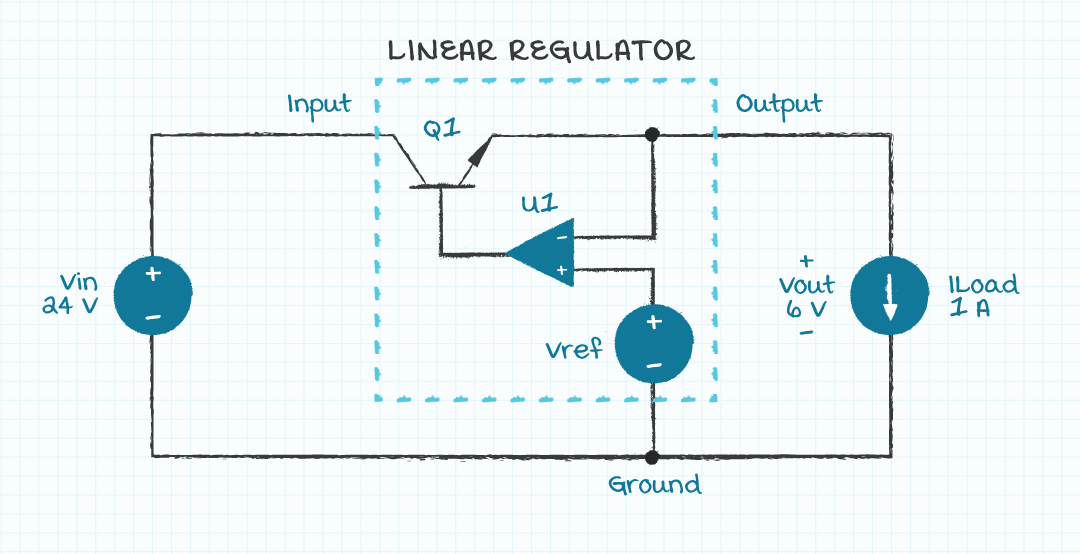
Looking at Figure 1, you can see that all we have between the input and output is a transistor (Q1) which is also called the pass element. This means that the voltage across the transistor (Q1) is the difference between input and output.

We can re-write this to solve for the output voltage.

From this we see that Vout is regulated by controlling the voltage across this transistor. Control of Q1 is accomplished using an op-amp, U1, and negative feedback. U1 senses Vout and compares it to a reference. If Vout is greater than the reference, then Q1 is driven less and the voltage across it increases. This causes Vout to decrease. If Vout was too low, Q1 would be driven more to lower the voltage drop across Q1, which would bring Vout up.
Linear Regulator Efficiency
To see why linear regulators are so inefficient we need to look at the load current path. Because the op-amp, U1, has high impedance inputs and is only driving the base of the transistor, we assume that no current goes in or out of it. With the op-amp removed, all that is left is a direct path from input to output meaning that the input current equals the output current.
We can now use this information to calculate the efficiency and power dissipated by the linear regulator. The input power is equal to Vin times Iin.

The output power is equal to Vout times Iout.

And the efficiency equals Pout divided by Pin.

This results in a power dissipation equal to the input power minus the output power.

For a load of only 6 W, the linear regulator is dissipating 18 W of power. That is a lot of power to dissipate in such a small package without any heatsinking or airflow. A typical thermal impedance of 20°C/W, of a linear regulator in a TO-220 package, would result in a temperature rise of 360°C from junction to ambient if no thermal management was applied.

This would clearly fail if no measures were taken to reduce the thermal impedance, such as heatsinking or airflow. The addition of a heatsink and airflow adds to the size, cost, and complexity of the system, which negates many of the benefits of using a linear regulator (i.e. cost and complexity). For the current example, a heatsink may be required in addition to airflow.
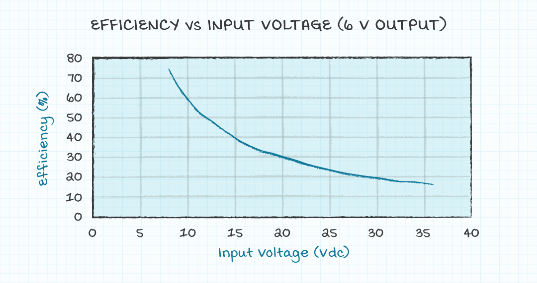
One last interesting effect of the input current equaling the output current is that the efficiency calculation can be simplified to Vout divided by Vin.
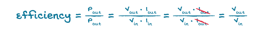
From this we can see the greater the difference between input and output the lower the efficiency (Figure 2) and the more power will be dissipated in the regulator. Making linear regulators undesirable in cases with large input voltage to output voltage ratios.
Switching Regulators
Switching regulators operate much differently than linear regulators. The main difference is related to how the transistor is controlled. Figure 3 shows a simplified buck regulator, which is a switching regulator that produces an output voltage that is lower than the input voltage, the same function as the linear regulator in our previous example.
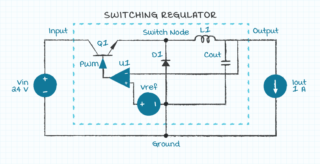
The circuit is similar in many ways to the linear regulator. The main physical difference is the diode and the L-C filter on the output. Like the linear regulator, the switching regulator uses an op-amp and negative feedback to control a transistor.
The first major difference, and the reason that it is called a switching regulator, is that the transistor is driven such that it is either fully on (ideally a short circuit) or fully off (ideally an open circuit). This is compared to the linear regulator where the transistor is controlled linearly in between fully on or off states. This transistor is switched on and off at high frequency and creates a square wave at the node connecting Q1, D1, and L1, which we call the switch node (Figure 4).
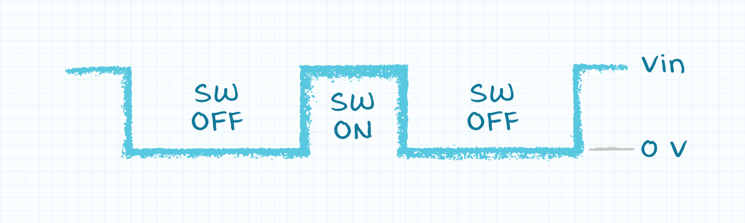
The output voltage is regulated by controlling the average value of the switch node voltage. For a fixed frequency operation, the average value is equal to the time that the switch is on divided by the period multiplied by the input voltage.

The ratio of on-time to period is known as the duty ratio and, in the buck regulator, is equal to the ratio of output voltage to input voltage. For our example this results in a duty ratio of 25% to convert a 24 V input to a 6 V output.

This square wave on the switch node feeds into the L-C network between the switch node and output. The L-C network is a low pass filter and only allows the average or dc value of the switch node to pass through to the output. So, by controlling the duty ratio, and thus the average voltage at the switch node, the switching converter can control the output voltage. This process is known as pulse-width-modulation (PWM).
Switching Regulator Efficiency
To see why this circuit is more efficient than the linear we can look at the switching regulator in both its on and off states under the same conditions as the example we had for the linear regulator.
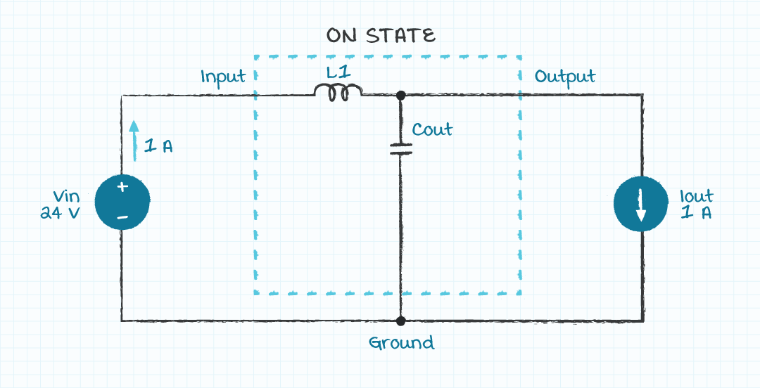
In the on-state, the transistor is driven fully on so that it represents a short. In this case current will flow from the input to the output, but the losses in the transistor are 0 W because the voltage across it is zero when current is flowing. The other elements in the current path (inductor, capacitor, and diode) are all ideally lossless and so during the on time, ideally no power will be dissipated.

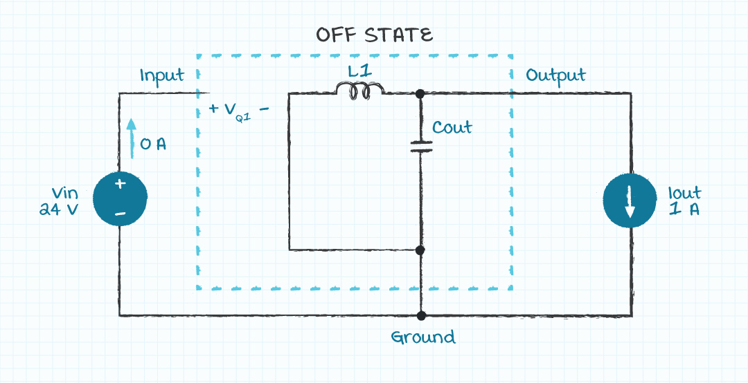
In the off-state, the transistor is fully off and represents an open circuit. In this case the voltage across the transistor is equal to the input voltage, but no current flows through it because it is an open circuit. The power dissipated in the transistor in this state is also 0 W. And again, the other components are assumed lossless.

This shows that in both on and off states, the switching regulator will ideally dissipate no power. This means that the upper limit of the efficiency is 100%, whereas the linear regulator has an upper limit equal to Vout/Vin.
Another way to look at this is that the input power during the on-time is equal to the input voltage times the output current, just like the linear regulator. However, during the off-time no current flows out from the input, so the input power is 0 W. The average amount of power into the regulator over one switching cycle is equal to the input power during the on-time times the average amount of time that the switch is on, which is the duty ratio. And because, in the case of the buck, the duty ratio is equal to the ratio of output voltage to input voltage, the following equation shows that the input power ends up equaling the output power, which means the efficiency is 100%.

In reality, the inductor, capacitor, and diode in the buck regulator are not ideal and will all incur losses decreasing the efficiency. The transistor will also not be ideal and have losses due to an on-state resistance along with losses due to switching. Therefore, the efficiency of a switching regulator is dependent on the chosen components and operating conditions. On the other hand, the efficiency of a linear regulator is independent of chosen components and is dependent only on the input and output voltage conditions.
Practical Implications of Poor Efficiency
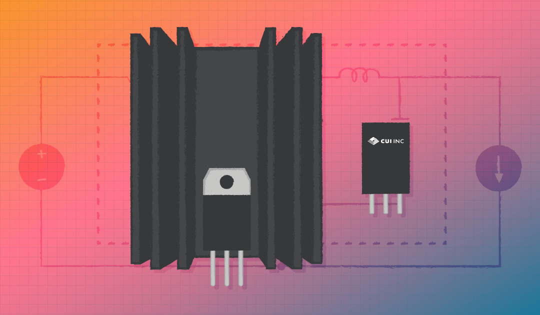
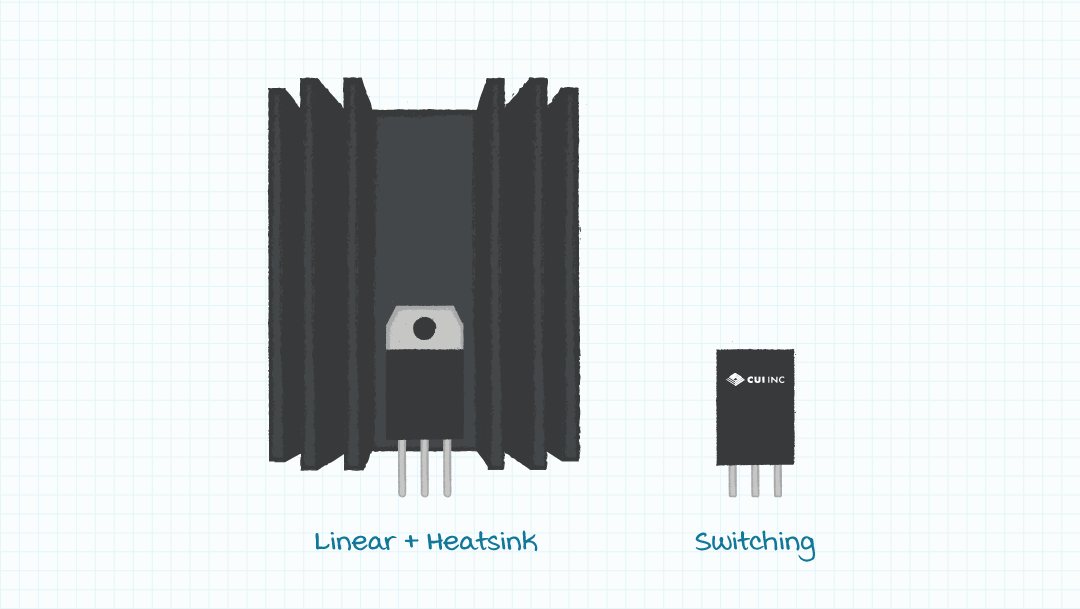
As mentioned earlier, one of the main reasons that linear regulators remain so popular despite their poor efficiency is their cost, simplicity, and familiarity. However, as discussed above, the poor efficiency and associated thermal issues can necessitate heatsinking and airflow, which act against these benefits. Switching regulators are an efficient alternative and while they may be more expensive and complex up front, they can decrease system cost and complexity by reducing the need for expensive and bulky thermal management devices. To get a feel for just how much thermal management is required for the example conditions, Figure 6 shows a side by side comparison of a linear regulator with a heatsink that with forced air cooling would allow the same operating temperature range, as with CUI’s off-the-shelf switching regulator.
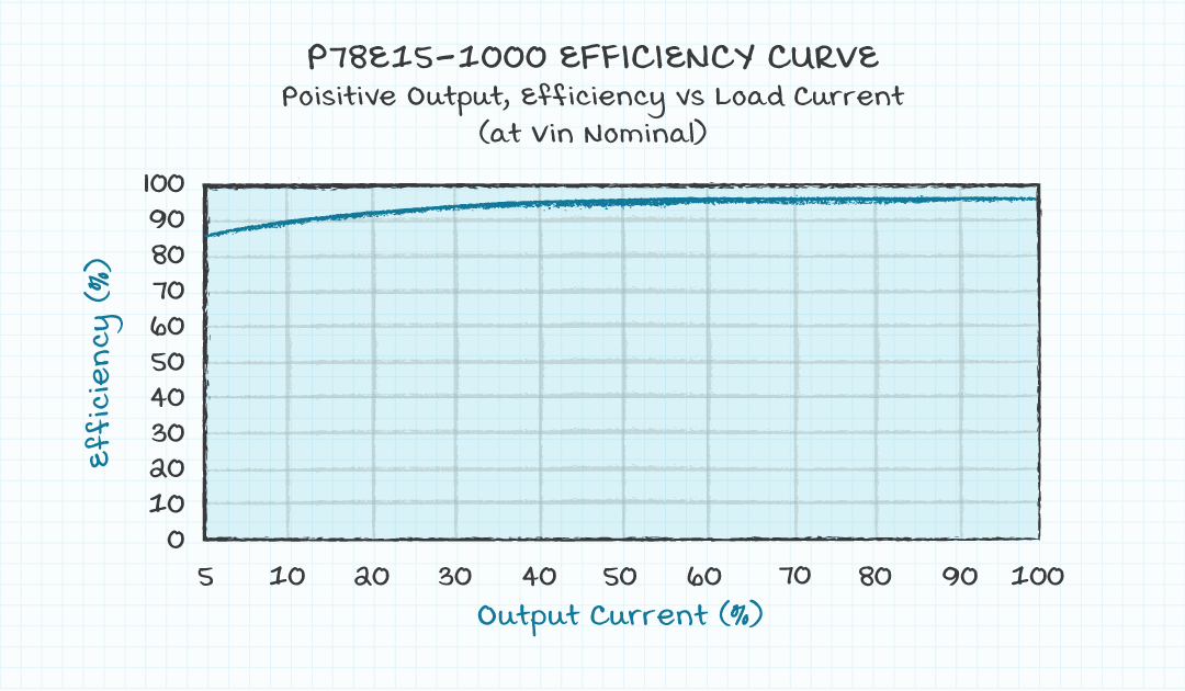
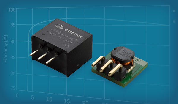
To ease the adoption of switching regulators in applications that would traditionally use linear regulators, CUI offers several series of switching regulators that are pin and footprint compatible with the classic 7800 series linear regulator in a TO-220 package. These regulators offer efficiencies up to 94% and can operate up to 36 V with outputs as low as 3.3 V without requiring any thermal management, at ambient temperatures exceeding 65°C (149°F).
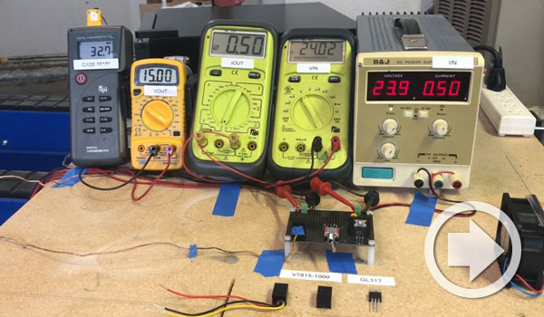
Video Demonstration
Checkout our CUI in the Lab video for a comparison between switching and linear regulators.
Conclusion
Linear regulators are a tried and true solution for non-isolated voltage conversion. However, their inherently poor efficiency can be a major concern if conducting large currents or operating at large input to output ratios. Switching regulators offer a highly efficient alternative. While switching regulators are more complicated internally and may be intimidating to those that are unfamiliar with them, CUI Inc offers a broad line of switching regulators, with a range of current ratings and packages, that are as easy to use as the classic linear regulator.
Fundamentals , Product Selection
You May Also Like
Have comments regarding this post or topics that you would like to see us cover in the future?
Send us an email at powerblog@cui.com


Ron Stull
Ron Stull has gathered a range of knowledge and experience in the areas of analog and digital power as well as ac-dc and dc-dc power conversion since joining CUI in 2009. He has played a key role on CUI’s Engineering team with responsibilities including application support, test and validation, and design. Outside of power engineering Ron can be found playing guitar, running, and touring the outdoors with his wife, where their goal is to visit all of the U.S. National Parks.