Building an LED Matrix with Arduino, Powered by CUI Supplies
September 8, 2020 by Ron Stull - 12 Minute Read
Background
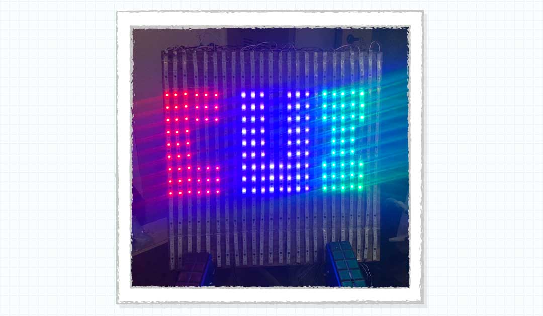
With COVID-19 keeping many of us at home, I've been using some of my extra time at home to go through my stockpile of power supplies and electronic components to see what I can do with them. My first project was to make use of some old programmable LED strips left over from the holidays. The result was a 24 x 18 matrix of RGB LED lights (432 RGB LEDs total). The matrix has a total of 144 controllable sections (24 x 6) programmed with a variety of selectable routines.
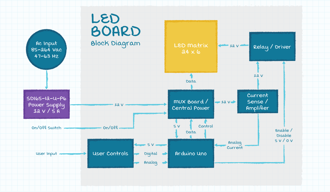
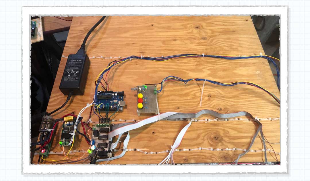
Board Overview
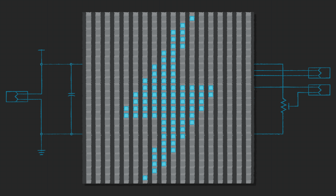
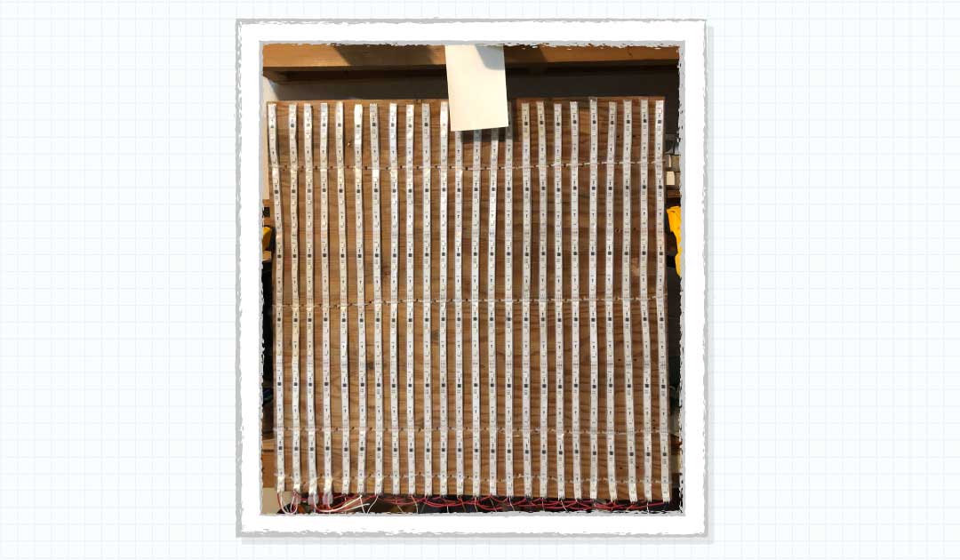
The board is made of a piece of plywood with 3 5-meter-long strips of LEDs cut up into a total of 24 smaller strips, each containing 18 LEDs. The color of the LEDs is controlled by an Arduino Uno in groups of three (6 groups per strip of 18 LEDs), based on user input from a potentiometer and three buttons. The board is powered by CUI's SDI65-12-U-P6, a 60 W, 12 V, 5 A, ac-dc power supply and two internal +/-5 V rails are supplied by CUI's V7805-1000s. A demultiplexer circuit is used to route data to the LED strips. The Arduino monitors the LED current and controls power to the LEDs through a relay.
| Category | Description | QTY |
|---|---|---|
| Controller | ARDUINO UNO ATMEGA328 EVAL BRD | 1 |
| LED Strips | 5m 150Leds WS2811 led strip programmable dream color light IP67 Tube waterproof white PCB | 3 |
| Power Supply | AC/DC DESKTOP ADAPTER 12V 60W | 1 |
| MUX Board | Demuliplexers and 5V regulator | 1 |
| Current Sense Board | Current sense and amplifier, with -5V regulator, 5V | 1 |
| Relay Board | Relay board, 12V | 1 |
| Button Board | User interface board, three buttons, one potentiometer, 5V | 1 |
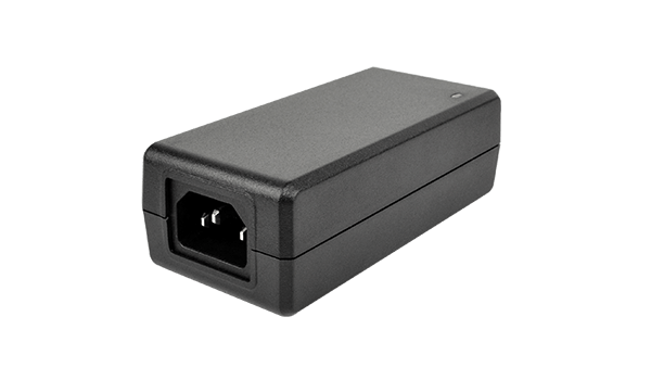
External Power
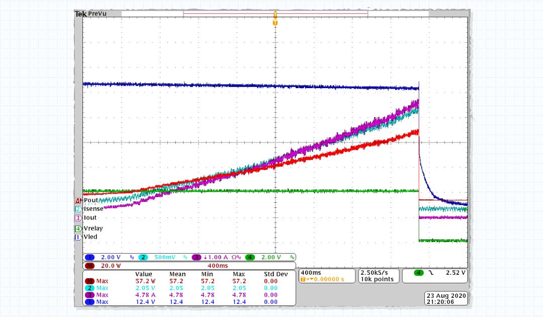
An SDI65-12-U-P6 external power supply is used as the main power source to the board. It can provide 12 V continuously, up to 5 A. Somewhere between 5 A and 7.5 A the power supply will go into over-current protection and hiccup until the load current falls back down. When this happens, the Arduino will lose power and reset unless its power rail can be held up long enough for the fault to be sensed and corrected. To sense the current and to prevent an OCP from resetting the controller, the LED strips are connected to the 12 V power supply through a current sensing circuit and a relay that is controlled by the Arduino.
Each LED has a maximum current of 18.5 mA. With 432 LEDs that puts the max current at 8 A, which means that under certain conditions it could trigger OCP. But that condition only applies when all red, green, and blue LEDs are on at the same time. A solid red or green at full brightness only requires 2.7 A. After testing I found that 4.5 A would be more than enough for everything I planned to do. The Arduino will monitor the sensed LED current and turn off the relay if the current exceeds ~4.6 A. This leaves 5 W for other circuits.
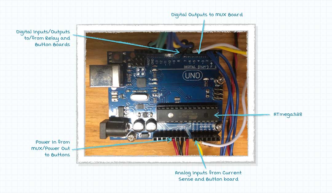
Arduino Uno
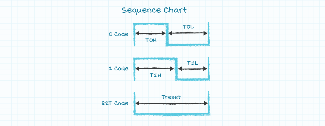
The Arduino Uno board, which is based around the Atmel ATmega328, is used to control the system. Communication with the LED strips (or the WS2811 that internally control them) is a single wire pulse-width based communication and is handled by the Adafruit NeoPixel library, which is included in the Arduino IDE. All of the communication, display routines, user interface, and relay control are programmed into and controlled by the Arduino board.
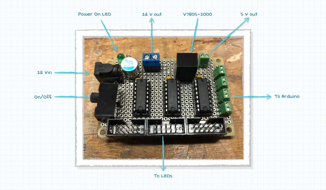
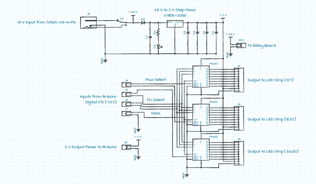
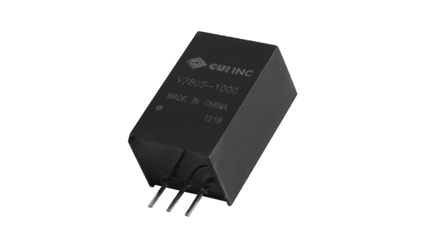
MUX Board
Each of the small strips have a single wire communication line that have been demultiplexed into a single communication line by the mux board, which is controlled by the Arduino Uno. The mux board also serves as the central power distribution point. External power, from the SDI65-12-U, plugs into the mux board directly. The 12 V from the power supply is distributed from the mux board to the relay board and the input of a V7805-1000 switching regulator which converts it to 5V for the demultiplexers. The 5V rail is also output to the Arduino and, through that board, to the button and current sense boards.
| Category | Description | Ref. | QTY |
|---|---|---|---|
| Connector | 2.0 x 6.5 mm, 5.0 A, Horizontal, Surface Mount (SMT), Dc Power Jack Connector | J8 | 1 |
| Connector | CONN HEADER VERT 10POS 2.54MM | J1, J2, J3 | 3 |
| Slide Switch | 5A/120V single pole double throw slide switch | S1 | 1 |
| Wire to board Terminal | TERM BLK 2P SIDE ENT 2.54MM PCB | J4, J5, J6, J7, J9 | 5 |
| Wire to board Terminal | TERM BLK 2P SIDE ENT 5.08MM PCB | J10 | 1 |
| Switching Regulator | DC-DC NON-ISOLATED, 2 A, 8~36 VD | DC1 | 1 |
| Ceramic Capacitor | CAP CER 0.1UF 50V X7R RADIAL | C3, C4, C5 | 3 |
| Electrolytic Capacitor | CAP ALUM 1UF 20% 50V RADIAL | C2 | 1 |
| Al Polymer Capacitor | CAP ALUM POLY 470UF 20% 16V T/H | C1 | 1 |
| LED | LED GREEN DIFFUSED T-1 3/4 T/H | D1 | 1 |
| MUX | IC 3-8 LINE DECODER/DEMUX 16-DIP | MUX0, MUX1, MUX2 | 3 |
| Resistor | RES 1.2K OHM 1/8W 5% CF AXIAL | R1 | 1 |
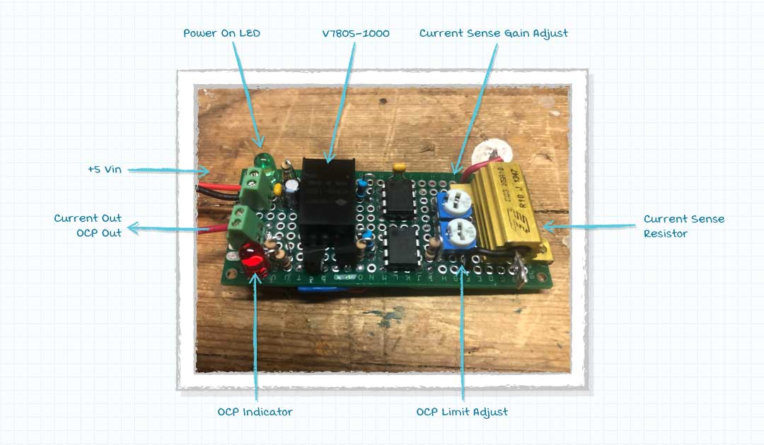
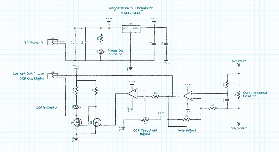
Current Sense Board
The Current Sense board is part of the over current protection (OCP) circuit. The current to the LEDs flows through a power resistor on this board and the voltage of this resistor, which is proportional to the LED current, is sensed and amplified by an op-amp and output to the Arduino. The amplifier gain is controlled by a potentiometer with a minimum gain of 1 and maximum gain of 11. It is normally set to 5, so that the output is 2.5 A/V of the input signal (2 V at 5 A). A comparator, whose threshold is set by a second potentiometer, detects if the OCP threshold has been crossed, which turns on an LED indicator and outputs a logic signal to the Arduino. This board is powered by the V7805-1000 5V rail coming from the MUX Board. It also internally creates the -5 V rail for the op-amp using a V7805-1000 in its inverting configuration.
| Category | Description | Ref. | QTY |
|---|---|---|---|
| Resistor | RES 5.1K OHM 1/8W 5% AXIAL | R2, R8 | 2 |
| OP-AMP | IC OPAMP GP 1 CIRCUIT 8DIP | U2, U3 | 2 |
| Resistor | RES 10K OHM 1/8W 5% AXIAL | R5, R6, R10 | 3 |
| LED | LED GREEN DIFFUSED T-1 3/4 T/H | D1 | 1 |
| LED | LED RED DIFFUSED T-1 3/4 T/H | D2 | 1 |
| Transistor | MOSFET N-CH 60V 200MA TO-92 | Q1, Q2 | 2 |
| Wire to board Terminal | TERM BLK 2P SIDE ENT 2.54MM PCB | J1, J2 | 2 |
| Ceramic Capacitor | CAP CER 0.1UF 50V X7R RADIAL | C2, C3, C4 | 3 |
| Switching Regulator | DC-DC NON-ISOLATED, 2 A, 8~36 VD | U1 | 1 |
| Resistor | RES 470 OHM 1/8W 5% AXIAL | R1 | 1 |
| Capacior | CAP ALUM 47UF 20% 25V THRU HOLE | C1 | 1 |
| Resistor | RES CHAS MNT 0.1 OHM 5% 16W | R4 | 1 |
| Ceramic Capacitor | CAP CER 0.01UF 50V X7R RADIAL | C5 | 1 |
| Trim Pot | TRIMMER 10K OHM 0.2W PC PIN TOP | R3 | 1 |
| Trim Pot | TRIMMER 50K OHM 0.2W PC PIN TOP | R7 | 1 |
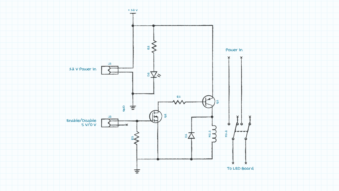
Relay Board
The relay board is a simple relay and driver. When the control input goes high the relay turns power on to the LEDs and when it goes low power is removed from the LEDs. This board runs on 12 V coming from the SDI65-12-U-P6 via the MUX Board.
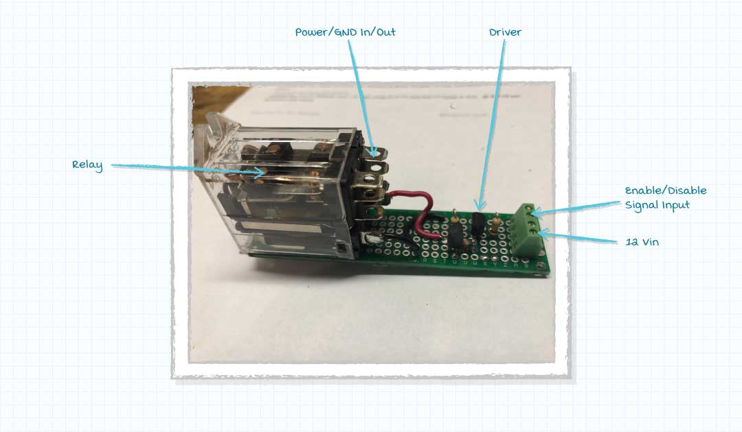
| Category | Description | Ref. | QTY |
|---|---|---|---|
| Wire to board Terminal | TERM BLK 2P SIDE ENT 2.54MM PCB | J1, J2, J3 | 3 |
| Transistor | Bipolar (BJT) Transistor PNP 40V 200MHz 600mW Through Hole TO-92 | Q1 | 1 |
| Transistor | N-Channel 60V 200mA (Ta) 400mW (Ta) Through Hole TO-92-3 | Q2 | 1 |
| Resistor | RES 2.2K OHM 1/8W 5% AXIAL | R1 | 1 |
| Resistor | RES 110K OHM 1/8W 5% CF AXIAL | R3 | 1 |
| Resistor | RES 1.2K OHM 1/8W 5% CF AXIAL | R2 | 1 |
| Relay | RELAY GEN PURPOSE DPDT 5A 24V | K1 | 1 |
Button Board
The user can control the brightness of the LEDs via a potentiometer. Three buttons allow the user to cycle through a variety of display routines and color settings. This board is powered by 5 V coming from the V7805-1000 on the MUX Board.
![[IMGALT]](/image/getimage/120531?typecode=m)
![[IMGALT]](/image/getimage/120532?typecode=m)
| Category | Description | Ref. | QTY |
|---|---|---|---|
| Buttons | SWITCH PUSHBUTTON SPST 1A 30V | S1, S2, S3 | 3 |
| Wire to board Terminal | TERM BLK 2P SIDE ENT 2.54MM PCB | J1, J2, J3 | 3 |
| Ceramic Capacitor | CAP CER 0.1UF 50V X7R RADIAL | C2 | 1 |
| LED | LED GREEN DIFFUSED T-1 3/4 T/H | D1 | 1 |
| Resistor | RES 4.7K OHM 1/8W 5% AXIAL | R1 | 1 |
| Electrolytic Capacitor | CAP ALUM 10UF 20% 16V RADIAL | C1 | 1 |
| Resistor | RES 110K OHM 1/8W 5% CF AXIAL | R2, R3, R4 | 3 |
| Potentiometer | POT 10K OHM 1/5W PLASTIC LINEAR | R5 | 1 |
Results
After the boards were soldered and assembled it was time to program some display routines. With the buttons the user can cycle through different routines, turn all of the LEDs on and off, and cycle solid colors, and a potentiometer allows the brightness of the LEDs to be adjusted. However, with limited memory, there's a limit to the number and complexity of the routines.
For the first routine (before I finished adding all of the LED strips) I replaced the potentiometer with an external analog input. A microphone and a level detection circuit were applied to this input and the mic volume controlled the LEDs.
Another routine was a bouncing square whose color would change when it hit an edge.
Finally, I added an all-white setting to test the OCP function. When the brightness is turned up it will trigger the OCP circuit. The following clip also demonstrates the button board toggling the programmed display routines.
You May Also Like

Have comments regarding this post or topics that you would like to see us cover in the future?
Send us an email at powerblog@cui.com


Ron Stull
Ron Stull has gathered a range of knowledge and experience in the areas of analog and digital power as well as ac-dc and dc-dc power conversion since joining CUI in 2009. He has played a key role on CUI’s Engineering team with responsibilities including application support, test and validation, and design. Outside of power engineering Ron can be found playing guitar, running, and touring the outdoors with his wife, where their goal is to visit all of the U.S. National Parks.