Designing with Multiple Output Power Supplies
March 17, 2020 by Ron Stull - 6 Minute Read
Introduction
Many electronics applications require multiple voltages to supply their various internal circuits. From fans and motors to logic and processing, the voltages may range from 48 V or greater down to 1 V or less. Instead of using an individual power supply or dc-dc converter for each of these rails, it may be advantageous to use a single power supply with multiple outputs. This can save time, space, and money in some applications. Understanding how multiple outputs are created and their various configurations is necessary to determine if a multiple output converter is the right choice for a specific application.
Methods for Creating Multiple Outputs
Power supplies can create additional outputs in a few different ways. Depending on the method used to create multiple outputs, the feasibility will vary per application based on performance and compatibility.
Transformers with Secondary Windings
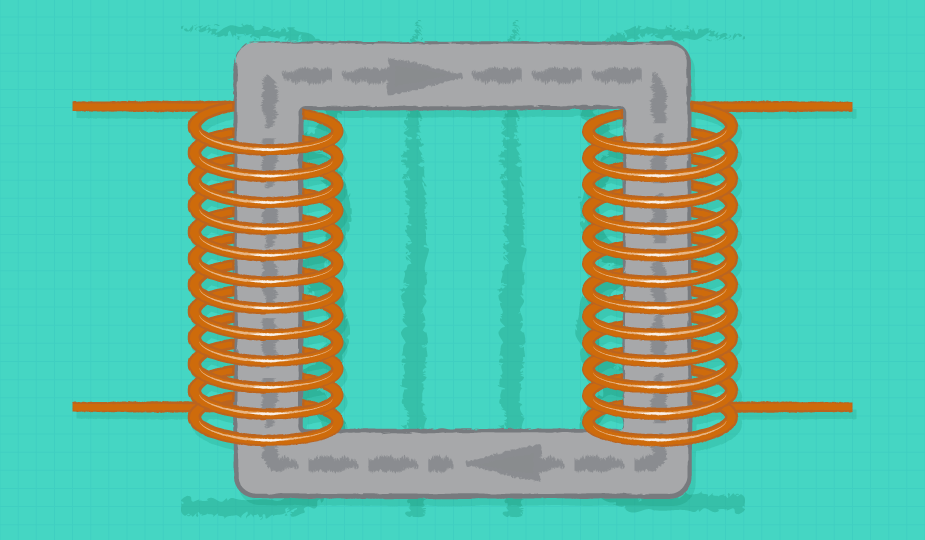
The simplest method for obtaining multiple outputs is to add secondary windings to the transformer or choke. The voltage of secondary windings (Vsec) on a transformer is related to the primary voltage (Vpri) through the turns ratio (n); which is the ratio of number of secondary turns (Ns), to the number of primary turns (Np). This is illustrated in Equation 1 and 2.
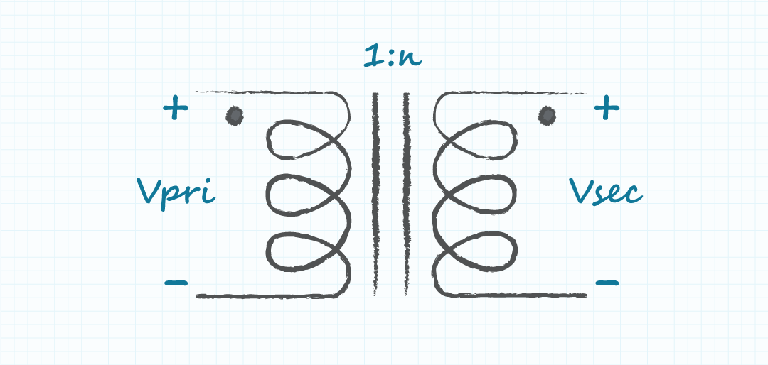
For example, if the primary voltage is 120 V and the turns ratio of the secondary is 0.1, the secondary voltage would be 12 V. A second output of 24 V could be obtained by adding an additional secondary winding with a turns ratio of 0.2.
Coupled Chokes with Secondary Windings
In topologies that use a coupled choke rather than a transformer, such as the flyback, the relationship between primary and secondary does not follow Equation 1. However, the relationship between secondary voltages and turns ratios does, making it just as easy to add additional outputs. By substituting the main output voltage (Vout1) into equation 1 for Vpri, and our desired voltage for an additional output (Voutn), we can still calculate the required turns ratio even though the primary to secondary relationship has changed (Equation 3).
Regulators and Additional Converters
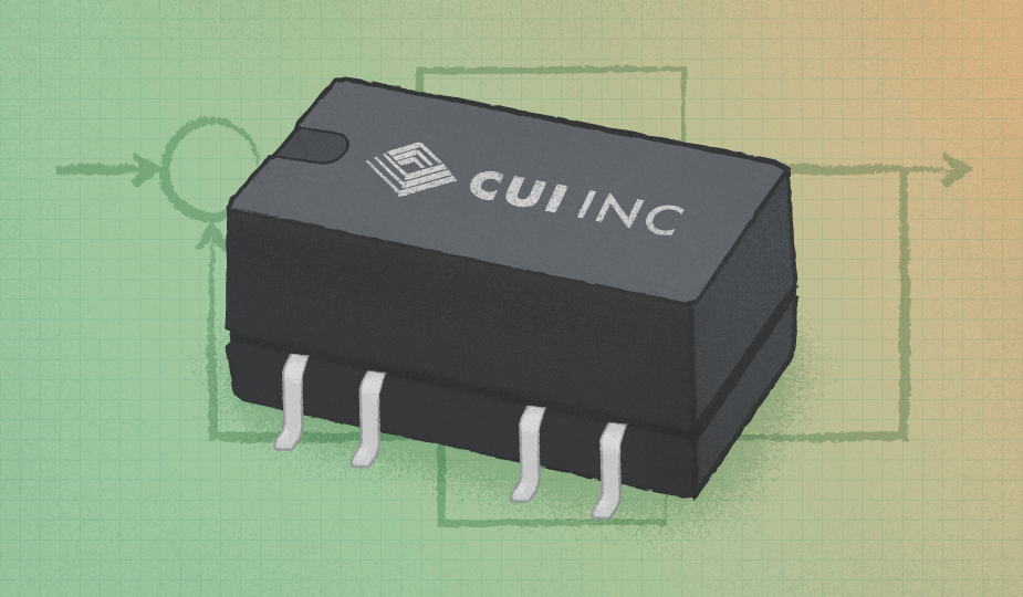
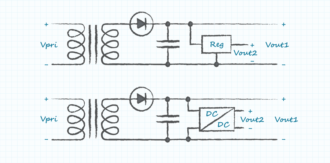
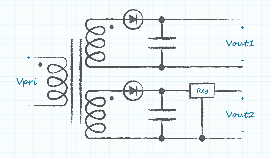
Another possibility is to add a regulator or an isolated dc-dc converter powered from the main output. Because the input of such a scheme has already been isolated from the primary and the voltage has already been stepped down, additional converters can be made smaller and less expensive than converting an additional voltage from the primary.
Considerations and Feasibility
Depending on how the additional outputs were derived, there are several details that can affect how multiple outputs will behave in an application, or whether a certain method should be used at all.
Isolation
The first thing to note is how the outputs are isolated, specifically whether or not they are isolated from each other. A common configuration is the center tapped transformer. In this configuration, the center point of the secondary winding is brought out to create two voltages, each equal to half of the voltage that is seen across the entire winding. This is a useful configuration when positive and negative voltages are needed, such as with an op-amp. By using the center-tap as the output ground you obtain positive and negative outputs. While the outputs of this configuration are all isolated from the primary side, they are not isolated from each other. This means that they reference the same ground potential and cannot be separated from one another to power circuits returning to different grounds (Figure 3). While the shared ground is inherent in a center tapped output, the return of any windings may be tied together, making these outputs non-isolated with respect to each other. For example, the negative terminals of Vsec1 and Vsec2 (bottom of Figure 3) could be tied together, leaving them non-isolated from one another.
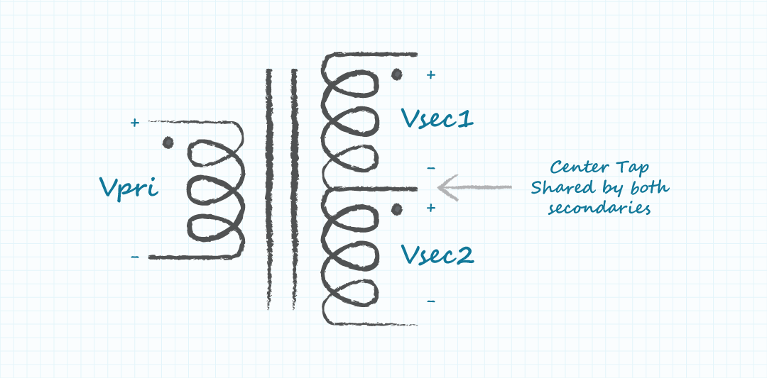
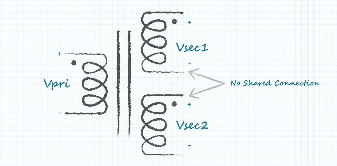
While outputs with shared grounds can be useful in some applications, in others the shared ground can cause problems. Powering multiple rails at different return potentials requires isolation between those outputs. For example, attempting to power a circuit such as a high-side gate drive requires a floating output whose reference is not fixed and not tied to circuit ground. If a ground referenced output is also required in the application, then it would require the second output to be isolated from the first and therefore a center tapped configuration could not be used.
Regulation
The next item to be aware of is the regulation of secondary outputs. Often it is only the main output that is actively regulated. The feedback loop will be closed around this main output and all other outputs will be passively related to it. Because of this, the tolerance of additional rails may be quite a bit lower than the regulated output. In addition to the absence of a closed loop, unregulated outputs are affected by the load on the main output. At light loads the coupling between the outputs diminishes. Because of this, there is often a minimum load specified on the main rail in order to keep the additional voltage within tolerance. The regulation of center tapped outputs can also be affected by unbalanced loads. For optimal performance the loads on each output should be kept as similar as possible. As discussed above, external regulators or dc-dc converters can be applied to these outputs to improve regulation (Figure 4).
Power Rating
The final consideration is the total output power. When multiple outputs are involved, it is important to calculate the total combined power of all outputs and ensure that this value is within the maximum power spec. Depending on the power supply, the power rating of the main output voltage may or may not include loading of the additional rails. If the additional outputs are in use, their output power may need to be subtracted from the power rating of the main rail.
Conclusion
Modern electronic systems often require multiple voltages to power their various circuits and components. Rather than using several supplies to power each rail separately, it can often save time, space, and money to use a multiple output power supply. However, while this may work well in some applications, it may cause problems in others. Understanding the behavior and relationship of these outputs is important for a design to be successful. CUI offers a wide selection of multiple output power supplies and can help you find the one that's best for your application.
Fundamentals , Product Selection
You May Also Like
Have comments regarding this post or topics that you would like to see us cover in the future?
Send us an email at powerblog@cui.com
