Isolated vs Non-Isolated Power Converters
December 3, 2019 by Ron Stull - 7 Minute Read
What's the Difference Between Isolated and Non-Isolated Power Supplies?
In short, an isolated power converter isolates the input from the output by electrically and physically separating the circuit into two sections preventing direct current flow between input and output, typically achieved by using a transformer. A non-isolated power converter has a single circuit in which current can flow between the input and output. For those not familiar with power supplies this leads to additional questions: What are the benefits of isolated vs non-isolated power supplies? And how do I know which one I need for my application?
Isolation Basics
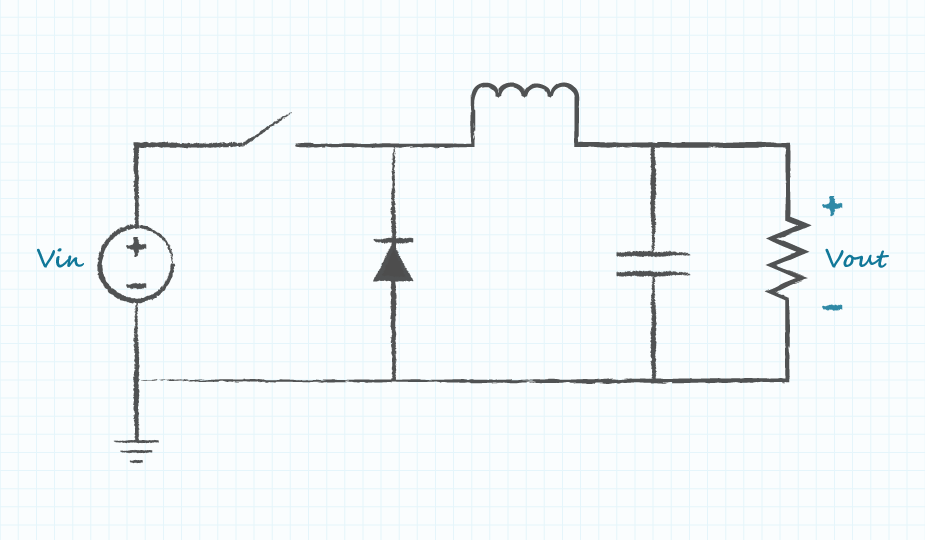
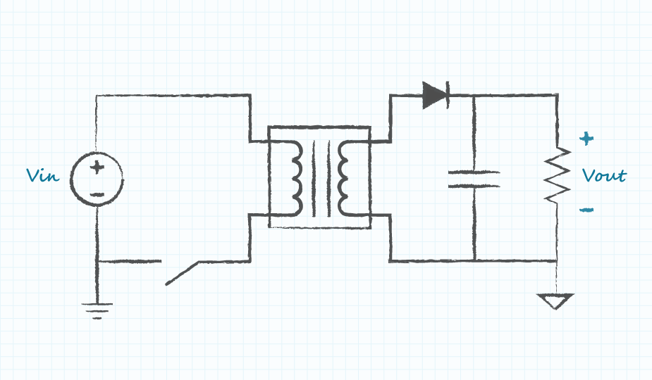
Galvanic isolation (usually simplified to just isolation) is the physical and electrical separation between one section of a circuit and another. A result of isolation is that each of the isolated circuits has its own return or ground reference. In a non-isolated converter, as shown on the left side of Figure 1, the input and output share a common ground and current can flow between them. However, in an isolated converter, as shown on the right side of Figure 1, the input and output return to their own independent ground and there is no path for direct current from one to the other.
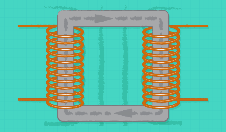
Even though current is not permitted to flow between input and output in isolated converters, power and information must still be transferred from one side to the other. There are several ways to do this, but power converters generally rely on two; power is transferred through electromagnetic fields using transformers or coupled inductors and signals cross the isolation using signal transformers or optically through opto-isolators.
Isolation is not absolute. At high enough voltages, the insulation will break down and current will flow. Datasheets will usually list the isolation voltage, which is the voltage which may be applied across the isolation for a short duration without current flowing. The isolation rating should not be confused with the working voltage, which is the maximum voltage that may be applied continuously across the isolation without isolation breakdown.
Benefits of Isolation
There are several cases where an isolated power supply may be required or provide some benefit in an application. These include safety compliance, the breaking of ground loops, and level shifting.
Safety Compliance
Safety requirements are a common reason to use an isolated power converter. For converters powered from high and potentially hazardous voltages (such as ac-dc converters powered from ac mains) isolation separates the output from dangerous voltages on the input.
When safety is the concern, the insulation grade must also be considered. Safety standards should be reviewed to determine what level of insulation is required for a given application. The insulation grade is divided into several categories including functional, basic, supplementary, and reinforced.
- Functional insulation: is the most simple and, while providing isolation, it does not provide any protection against electric shock.
- Basic insulation: provides a single layer of protection against shock.
- Supplementary insulation: is basic insulation plus one additional barrier for redundancy.
- Reinforced insulation: is a single barrier equivalent to two layers of basic.
Breaking of Ground Loops
Because the input and output of isolated supplies do not share a ground, they can be used to break up ground loops. Circuits that are sensitive to noise can benefit from this by having their ground broken up and separated from noisy circuits that could cause problems.
Floating Outputs and Level Shifting
Another benefit to isolated converters is a floating output. Isolated outputs, while having a fixed voltage between output terminals, don't have a defined or fixed voltage relative to voltage nodes in circuits from which they've been isolated, and are said to be floating. However, a floating output may have one of its terminals connected to another circuit node to fix it to that voltage. This fact can be used to shift or invert the output relative to another point in a circuit.
For example, Figure 2 shows how connecting the +Vout terminal to the input ground terminal will force the output ground down below input ground by an amount equal to Vout. Before making this connection the voltage between Vin and Vout was undefined, this connection now provides a common potential to which each side is now related.
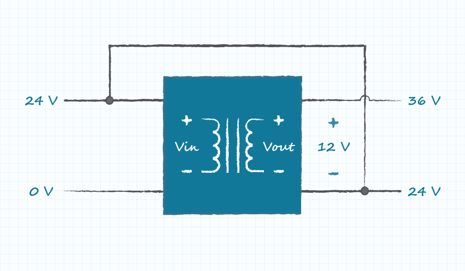
By connecting the output ground terminal to the +Vin terminal, as shown in Figure 3, the +Vout terminal will be equal to (Vin+Vout) relative to the input ground. In both this and the previous case, the isolation from input to output has been lost as the two sides now share a direct connection.
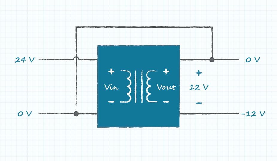
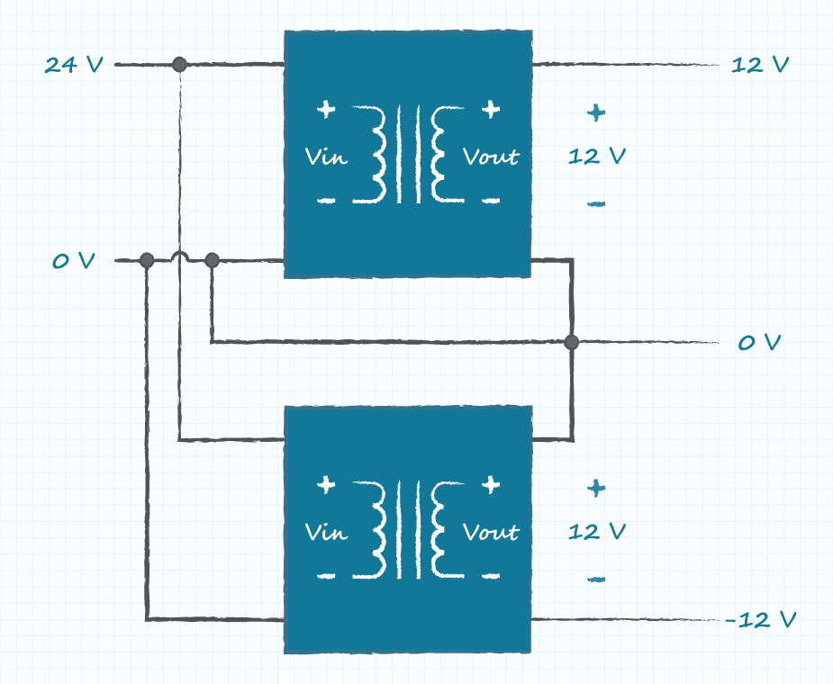
Multiple isolated converters with floating outputs may also be connected in series to increase the output voltage or create +/- rails, as shown in Figure 4.
Care should be taken to ensure that the outputs are truly floating. For example, if the output ground terminals of two isolated converters were connected to the chassis, they would no longer be floating relative to one another, and if the outputs were connected in series this would create a short across one of the converters as both terminals would be connected to chassis. In ac-dc converters it sometimes occurs that the output ground terminal is connected to earth, which means that it is no longer floating, even though isolated.
Benefits of Non-Isolated
While there are many benefits to isolation, there are also reasons to use a non-isolated converter including cost, size, and performance.
Cost Savings
Isolated converters tend to be more expensive than non-isolated. A major contributor to the cost difference is the use of a transformer in place of an inductor. Transformers tend to be custom built as opposed to the inductor in a non-isolated converter which can be purchased off the shelf. If a higher level of insulation is needed (such as that needed for safety compliance) the cost will further increase. In addition to the transformer, there are components, such as the opto-couplers, that may be added to an isolated design that wouldn't be necessary in a non-isolated. All of this adds to increased cost compared to a non-isolated design.
Smaller Size
Non-isolated converters tend to be smaller than isolated. The cost-adding components mentioned previously take up more space than those used in a non-isolated design. In addition to substituting an inductor for a transformer, non-isolated converters tend to operate at higher switching frequencies which will further reduce the size of the magnetic components and capacitors.
Efficiency
The efficiency and regulation of non-isolated converters also tend to be better than that of an isolated converter. The transformer and opto-couplers again are major contributors to the difference in performance. The absence of an isolation barrier allows for the output to be directly sensed and tightly controlled for better regulation and transient performance. Their small size also allows them to be placed closer to the load to reduce the transmission line effects.
Conclusion
The choice between isolated and non-isolated converters depends on many factors. Some applications require isolation for safety reasons, and others may benefit from a floating output by breaking up ground loops or shifting of reference voltages. However, where isolation is not required, a non-isolated converter may provide a decrease in cost, size, and/or an increase in efficiency. Understanding the costs and benefits of isolation is important in choosing the right converter for an optimized design.
Fundamentals , Product Selection
You May Also Like

Have comments regarding this post or topics that you would like to see us cover in the future?
Send us an email at powerblog@cui.com


Ron Stull
Ron Stull has gathered a range of knowledge and experience in the areas of analog and digital power as well as ac-dc and dc-dc power conversion since joining CUI in 2009. He has played a key role on CUI’s Engineering team with responsibilities including application support, test and validation, and design. Outside of power engineering Ron can be found playing guitar, running, and touring the outdoors with his wife, where their goal is to visit all of the U.S. National Parks.