Reliability Considerations for Peltier Modules
Peltier modules, also known as thermoelectric coolers (TEC) or thermoelectric modules (TEM), are solid state devices which transfer heat when electrical power is applied. As with many components, the reliability of Peltier modules is of great importance in applications, so it is beneficial to have some basic knowledge regarding their construction and proper implementation. This blog post will provide an overview of Peltier module construction followed by a summary of common failure mechanisms and ways to improve TEC reliability.
Peltier Module Construction
Peltier modules are solid state devices which contain no moving parts and operate within a wide range of temperatures. The construction of Peltier modules has been addressed in this CUI Devices blog, but here is a quick refresher to aid in the discussion.
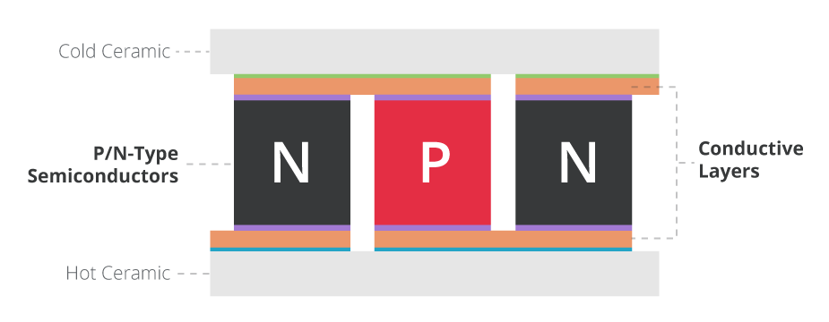
The construction of Peltier modules consists of positive and negative doped pellets of semiconductor material placed between two electrically insulating but thermally conductive plates of ceramic. Conductive patterns of metal are plated on the inner surfaces of each of the ceramic plates and the semiconductor pellets are soldered to the conductive patterns. This module configuration places all of the semiconductor pellets electrically in series and mechanically in parallel. The series electrical connections enable the desired thermal effects and the parallel mechanical configuration causes heat to be absorbed by one of the ceramic plates (the cold side) and released by the other ceramic plate (the hot side).
Peltier Module Failure Mechanisms
The most common failure mechanism of Peltier modules is mechanical fracturing of the semiconductor pellets or the associated solder joints. These fractures initially do not propagate completely through the pellet or solder joint and can be detected by a rise in the series resistance of the device. This rise in the Peltier module's resistance causes a reduction in its overall "efficiency," but a complete failure can occur if a fracture propagates completely across a semiconductor pellet or solder joint.
Mechanical Tension or Shear
Typical Peltier module applications involve placing an object to be cooled on the cold plate of the module and a heat sink on the hot side. Mechanical failures are likely to occur if the heat sink and the object to be cooled are adhered to the ceramic plates without any other mechanical structure to support the cooled object and heat sink. Using only the Peltier device to support the object or heat sink may cause large shear or tension loads across the module. Peltier modules are not able to withstand large tension or shear forces between the heat sink and the cold plate and may break if such forces are applied.
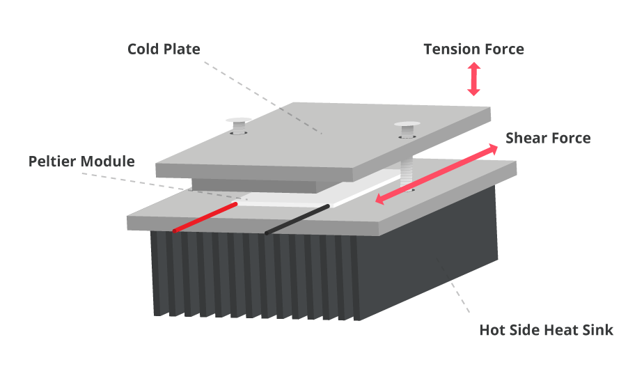
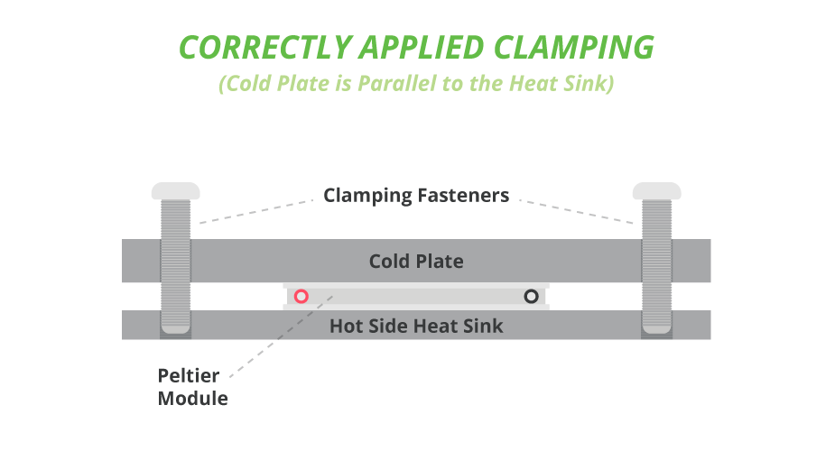
In most applications, the heat sink and the object to be cooled are clamped together with the Peltier module in between. This mechanical configuration is used because Peltier modules can withstand large compressive forces from the clamps, while the clamps absorb any shear or tension stress developed between the object and heat sink.
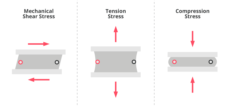
Mechanical Compression
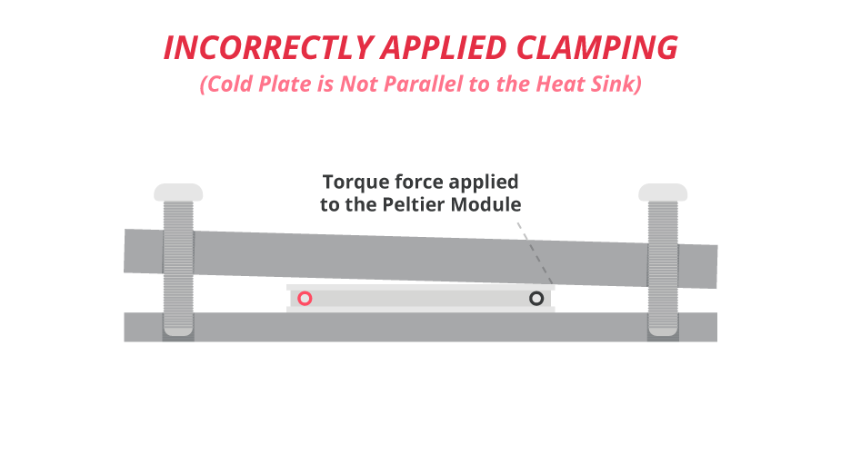
Although Peltier modules tolerate large compressive loads, heat sinks and objects to be cooled must be applied in such a way that the clamping force is even across the Peltier module. Uneven clamping forces create torques as well as compressive forces between the ceramic plates, which can lead to mechanical failure.
The mechanical constraints creating the compressive clamping force across a Peltier module must be applied carefully and in an even manner. Doing so will minimize the torque stresses applied to the module and minimize the possibility of damage.
Thermal Cycling
The ceramic plates and semiconductor pellets used to construct Peltier modules have associated coefficients of thermal expansion (CTE). Mismatch of the ceramic and semiconductor CTEs cause mechanical stresses which can initiate fractures in the semiconductor pellets and solder joints as the module is heated or cooled. In addition to the change in absolute temperature of Peltier modules, thermal gradients across the device and rapid rates of change in its temperature cause mechanical stresses due to the CTEs. Operation at extreme temperatures, with large temperature gradients, and at high temperature slew rates all produce increased mechanical stresses which can cause device failures.
Contaminants
The semiconductor pellets, solder joints, and metalized conduction paths in Peltier modules can be exposed to contamination from outside sources, which can also lead to failures. A common solution to minimize the exposure to contamination is to apply a bead of sealant around the perimeter of the module, between the two ceramic plates. Silicone rubber is a common sealant due to the mechanical compliance of the material, but in severe operating environments the silicone rubber may not be effective as a vapor barrier. Epoxy can be used as the perimeter sealant where high vapor concentrations are present. However, epoxy is not typically as mechanically compliant as silicone rubber.
Peltier Module Reliability Improvements
As mentioned above, mechanical stresses can cause cracks to develop in a Peltier module's solder joints and semiconductor pellets. CUI Devices' arcTEC™ structure, found in its family of Peltier modules improves module performance, reliability, and cycle life thanks to its unique construction that combats the effects of thermal fatigue. It starts by replacing the solder joints on the cold side of the module with an electrically conductive resin. This resin is more mechanically compliant than solder and thus helps to minimize the stresses and fracturing that occurs in traditional Peltier module structures. The remaining solder joints in the arcTEC structure are made with high temperature antimony solder (SbSn, 235°C) rather than the more common and lower temperature bismuth solder (BiSn, 138°C). Antimony solder tolerates mechanical stress better than bismuth solder, which helps to improve Peltier module reliability. CUI Devices' Peltier modules are also supplied with a silicone rubber vapor barrier, adding to their mechanical compliance. Other vapor barriers, such as epoxy, are available upon request.
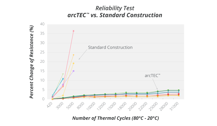
Testing below demonstrates the reliability improvements of the arcTEC structure versus conventional Peltier modules. With failures increasing as resistance increases, the chart shows the rapid rise in resistance of traditional module construction compared to the more consistent performance of the arcTEC structure over a greater number of thermal cycles.
Conclusion
It can be difficult to quantify the reliability of Peltier modules due to the large dependence upon operating conditions. However, many factors have been discussed which contribute to degradation of their reliability. Some of the factors are related to the mechanical installation of the modules (shear and torque stresses), while other factors are related to the operating conditions (temperature, temperature gradient, and temperature slew rate). Chemical contamination can also be an issue in some applications. Improved Peltier module assembly technologies, such as those used in CUI Devices' arcTEC structure, help to mitigate mechanical failure mechanisms and thus contribute to improved reliability. CUI Devices offers a range of Peltier devices with a variety of sizes and thermal ratings to best match the specific needs of your application.

 Tags:
Tags:
Additional Resources