Selecting Output Capacitors for Power Supply Applications
December 6, 2022 by Bruce Rose - 10 Minute Read
A Simple View of Power Delivery
When we look at almost any power supply application circuit there will be capacitors on the output of the power supply located at the load. One question often asked of power supply vendors is “Why are the output capacitors required on a power supply and how are the capacitors selected?”. In this discussion we will address both parts of that question.
A simple view of a power delivery system is a power supply and a load with some conductors connecting the output of the power supply to the load. In most applications what is called a ‘power supply’ is a voltage supply, in that the supply provides a constant voltage to the load up to its maximum rated power level. Now that we have discussed the difference between a voltage supply and a power supply, we will use the terms interchangeably in this discussion but with the understanding that the supply we are discussing is a voltage supply.
Upon closer examination it can be understood that the power supply attempts to deliver a constant voltage to the load, but when the load current changes the voltage delivered to the load also changes. The changes in the voltage delivered to the load come from both changes in the output voltage directly at the power supply and from voltage drop along the conductors connecting the power supply to the load.

Sources of Voltage Deviations
In many designs, the primary changes in the output voltage from the supply due to changes in the load current are caused by the bandwidth of the power supply and the parasitic impedances of the conductors between the power supply and the load. We will briefly discuss these characteristics before looking into how bypass capacitors can be used to compensate for the characteristics.
Power Supply Bandwidth
Power supplies are constructed by comparing the actual output voltage from the power supply to a reference voltage internal to the power supply and then adjusting the commanded output voltage to minimize the difference between the actual voltage and the desired voltage.
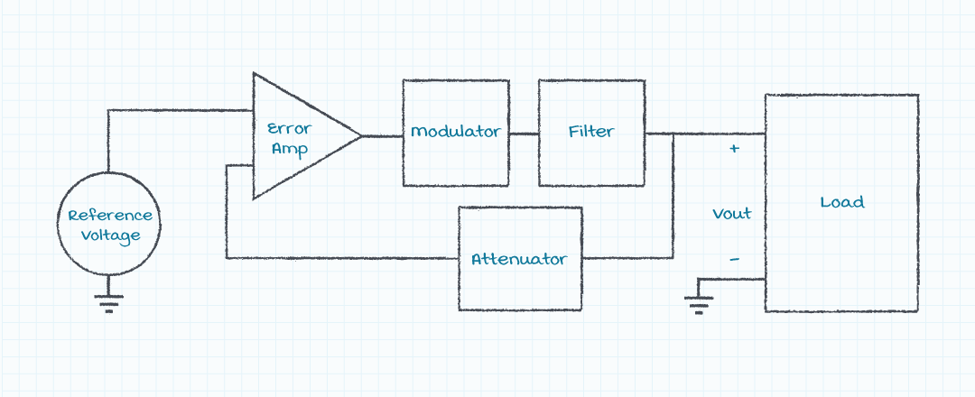
Since the power supply topology is a feedback loop, there will be a bandwidth associated with the response of the power supply that is dependent upon the parameters of the system. Most power supplies are switching supplies and the bandwidth is thus limited to about one tenth to one quarter of the switching frequency. Assuming that in most switching power supplies the switching frequency is between about 30 kHz and 300 kHz, the bandwidth will thus be between 3 kHz (30 kHz/10) and 75 kHz (300 kHz/4). For this discussion, we assume a 10 kHz bandwidth for the power supply.
The 10% ~ 90% rise time of a single pole system can be approximated as Tr = 0.35/BW (Tr is the 10~90 % rise time of the system in seconds and BW is the bandwidth of the system in Hertz), thus a system with a 10 kHz bandwidth will have a rise time of 35 µs (Tr = .35/104 = 35 µs). The rise time of the power supply can be viewed as an approximation of how long it will take for the power supply to react to a step load current. If the step load current is an increase, then the voltage at the load will droop while the supply is reacting to meet the new load current demand. If the step load current is a decrease, then the voltage at the load will jump up while the supply is reacting to meet the new load current demand.
Capacitors placed at the load can act as charge reservoirs to buffer the difference between the load current transient and the current being supplied by the voltage source. Reaching back to beginning electronics we remember equation 1, which shows the relationship between the current, capacitance, and voltage changes over time. This equation can also be rearranged to solve for the voltage deviation caused by a change in current if the capacitance is known, or the capacitance needed to limit the voltage deviation caused by a change in current.

For example, assuming a 10 kHz bandwidth, if the output voltage must be kept within 120 mV of the nominal output, and the change in output current is 2 A, then the minimum capacitance required at the load would be 583 µF.

Power Conductor Parasitic Impedances
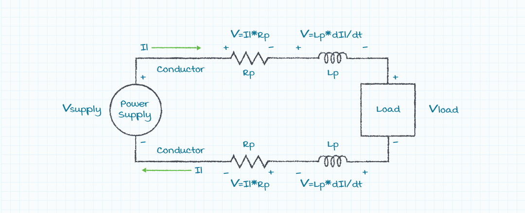
Associated with the conductors between the power supply and the load there will be parasitic resistance and inductance, shown in figure 3. The parasitic resistance and inductance will cause the voltage delivered to the load to vary with changes in the load current. The voltage present at the load (Vload) will be the supply voltage (Vsupply), reduced by the parasitic resistance (Rp) multiplied by the load current (I), and is also reduced by the parasitic inductance (Lp) multiplied by the change in the load current with time (dI/dt), shown in equation 3.

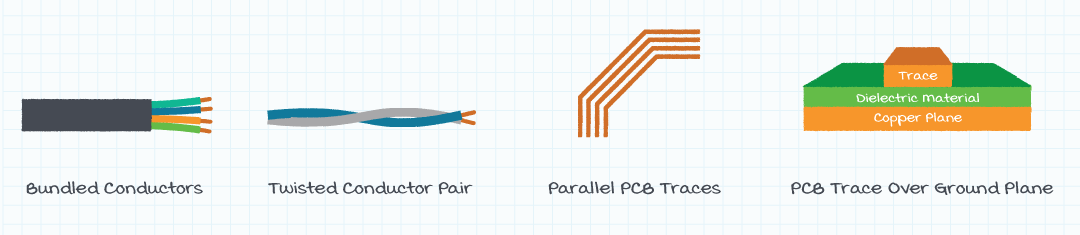
The bad news is the voltage excursions created by a load transient and the parasitic impedance of the power delivery conductors can be difficult to calculate because they depend upon both the change in the load current and the rate of change of the load current. The good news is it is relatively easy to specify power delivery conductors with low parasitic resistance and inductance. Low parasitic resistance can be achieved by using large area conductors, such as large diameter wires or wide PCB traces. Low parasitic inductance can be achieved by making a small loop area between the two power conductors. Common methods of minimizing the loop area between conductors, shown in figure 4, are running cables in a tight bundle, twisting two conductors around each other, running PCB traces near each other, and running a power trace above a ground plane.
Capacitor Types
The previous sections have discussed how to determine how much capacitance to place at the load to reduce voltage excursions to a particular level, but there also are concerns regarding what types of capacitors should be placed at the load. One of the first criteria for selecting the capacitors should probably be how much capacitance is required. When the capacitance required is greater than ones or tens of microfarads, either tantalum or electrolytic capacitors may be the preferred capacitor technology. Capacitors made with these technologies are reasonably compact and affordable. When capacitors required are less than tens of microfarads, ceramic capacitors are often the preferred choice as they are more compact and affordable in those sizes. It should be noted that the capacitance value of many ceramic capacitors is greatly reduced when a dc voltage is applied that is close to the voltage rating of the capacitor. A web search on this topic will provide more information regarding this issue.
Parasitic Elements in Capacitors
In addition to size and cost concerns, the values of the parasitic inductance and resistance in a capacitor may affect the selection of technology for capacitors. The internal conductors in a capacitor have associated resistance and inductance that affects the performance of the capacitor.
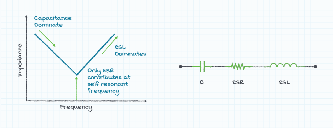
A simple graph of the impedance of the capacitor model shows behavior dominated by the capacitor value at lower frequencies, dominated by the ESL at higher frequencies and dominated by the ESR value near the resonant frequency of the C and ESL values (figure 5). It should be apparent from an examination of the impedance graph that while the value of required capacitance has been discussed earlier, the ESL and ESR will determine the effectiveness of the capacitance at higher frequencies.
Placing Capacitors in Parallel
Due to the nature of their construction, electrolytic capacitors tend to have higher values of ESL and ESR, tantalum capacitors have lower values of ESL and ESR, and ceramic capacitors have the lowest values of ESL and ESR. Placing capacitors in parallel will increase the value of C and reduce the ESL and ESR. Using capacitors of different construction technologies when placed in parallel with both reduce the impedance and will also spread the impedance affects wider in frequency.
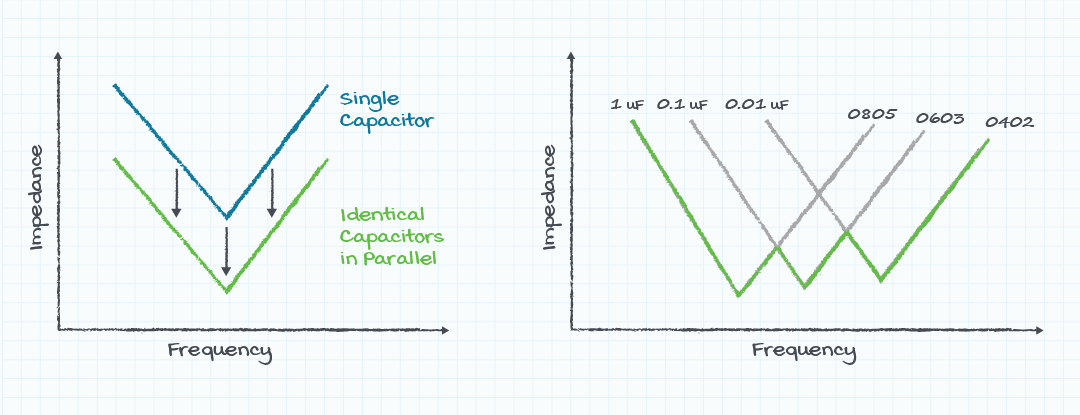
Placing smaller value ceramic capacitors with smaller values in parallel with electrolytic capacitors of larger values is effective because the electrolytic capacitors address the higher energy and lower frequency issues while the ceramic capacitors address the higher frequency transients. The value of the ceramic capacitors can be much less than that of the electrolytic capacitors because the energy in the transients at higher frequencies will be much less than that at the lower frequencies.
Capacitor Purpose and Selection
Based upon our discussion it should now be understood that capacitors are often placed across the power supply terminals at the load to reduce the voltage excursions caused by load current transients and the finite bandwidth response of the power supply. The value and type of capacitor used will depend upon the bandwidth of the power supply, the magnitude of the load transient, the frequency components of the load transient, and the acceptable level of voltage excursion caused by the load transients. Additional details and support regarding these issues can be obtained by contacting the technical support team at power supply vendors, such as CUI.
Fundamentals , Product Selection , Testing & Failure Analysis
You May Also Like
Have comments regarding this post or topics that you would like to see us cover in the future?
Send us an email at powerblog@cui.com


Bruce Rose
During his many years in the electronics industry working in design, sales, and marketing, Bruce Rose has focused on analog circuits and power delivery. His range of work experience includes organizing and chairing international workshops, publishing and presenting in more than 40 technical conferences and journals, and having been awarded seven patents. While he enjoys his time at work, Bruce further enjoys the time he is able to spend with his family hiking, biking, and canoeing as well as pursuing his passion of full scale and model aviation.