CURRENT SHARING WITH POWER SUPPLIES
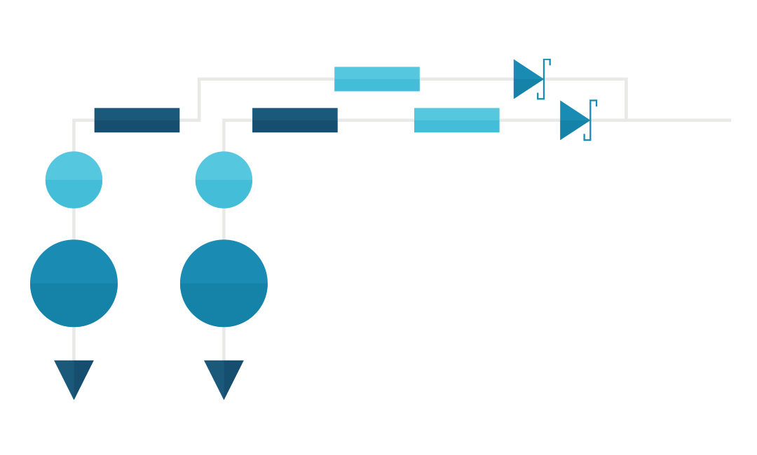
The need often arises to supply more current to a load than the output current rating of an available power supply. At such times it may be possible to connect two or more supplies in parallel in order to deliver the desired current to the load. Connecting the outputs of multiple power supplies in parallel will not guarantee the load current is shared between the units- in an acceptable manner. Many factors contribute to the potential challenges in configuring paralleled power supplies to share load current. Some power supplies are designed with dedicated circuits to be used when placed in parallel to ensure the load current is properly shared. Users should review the documentation from the vendors of such supplies to understand how to properly configure for current sharing. This paper will present some basic characteristics of power supplies and discuss the methods of paralleling units which do not have special provisions to enable them to be configured in parallel.
IDEAL VOLTAGE SOURCES
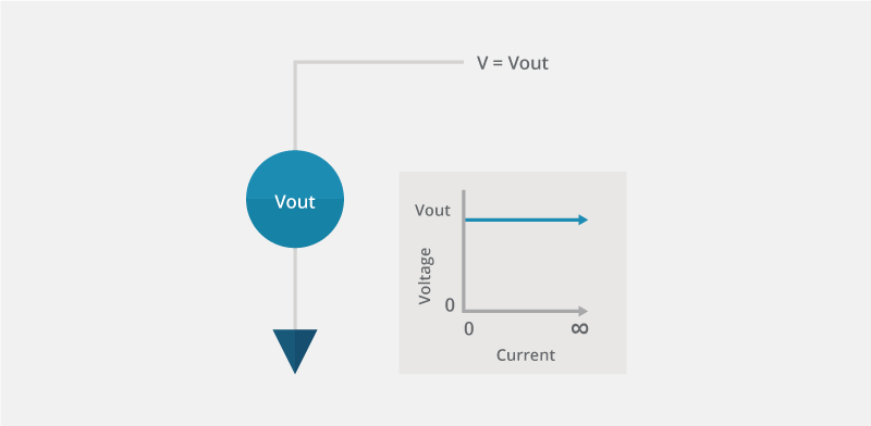
An ideal voltage source maintains a constant voltage and can deliver an unlimited amount of current. This implementation cannot be physically constructed since it requires the voltage source to be able to deliver an infinite amount of power as the load current rises. Although this ideal configuration cannot be physically realized, it is the basis upon which power supplies are designed.
VOLTAGE SOURCE WITH CURRENT LIMIT
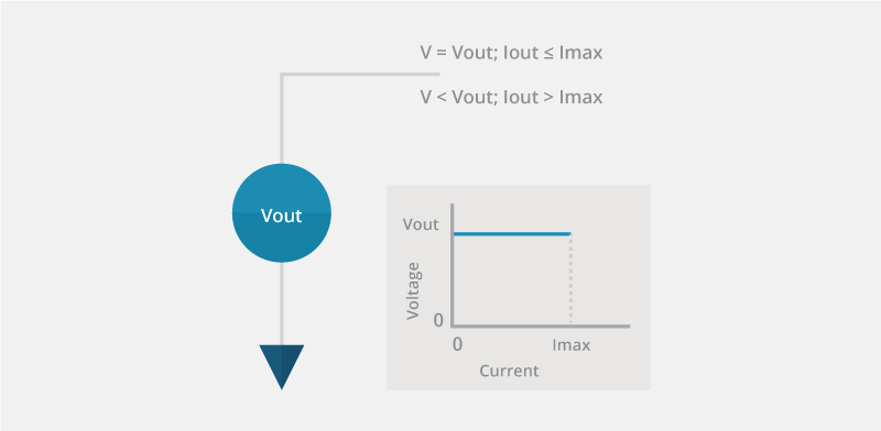
All real power supplies will have a limit to the amount of current that can be delivered to the load. At some load current the output voltage will collapse to zero volts. The designer of the power supply has the ability to control the behavior of the collapsing output voltage as the load current increases beyond the value for which the power supply is designed. Some possible options for current limit behavior include gradually reducing the output voltage as the current rises above Iout max or immediately shutting down the unit when the current reaches Iout max. The power supply can be designed to automatically recover from an over-current condition or it can be designed to require an external reset event. Supplies with many different types of current limit behavior can be used in parallel; the user must be aware of how to control the power supply if it does enter into current limit mode.
VOLTAGE SOURCE OUTPUT IMPEDANCE
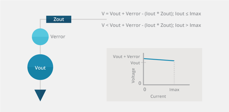
Almost all real voltage sources have positive, non-zero output impedance. When a voltage source has positive output impedance the output voltage drops as the load current increases. The change in output voltage with load current is characterized as load regulation in power supply specifications. Typically it is desired to have as little change as possible in output voltage with increasing load current; low voltage droop is achieved with low output impedance. Droop in output voltage with increasing load current is typically employed to enable current sharing between multiple power supplies.
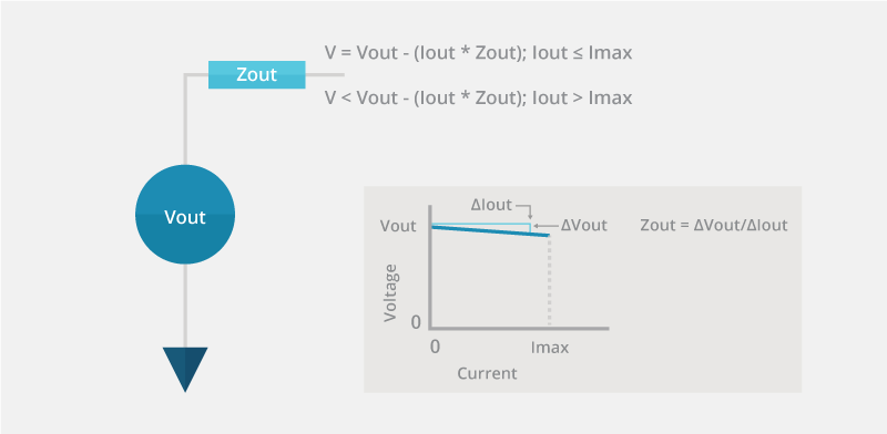
Some power supplies support remote voltage sensing in order to minimize the contributions of layout impedances to Zout. When using remote voltage sensing, degradation of load regulation due to the parasitic impedances is reduced by the action of the feedback loop. A later section will explain why remote voltage sensing may not be desirable in a current sharing application.
VOLTAGE SOURCE SET-POINT ERROR
When constructing real voltage sources there will be an error in the set-point voltage value. This error voltage can be either positive or negative and can be reduced to an acceptable level by controlling manufacturing tolerances or by trimming of the final product. A minimal error in the set-point voltage is advantageous when configuring power supplies to current share.
PARALLELING POWER SUPPLIES
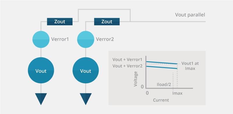
Perhaps one of the simplest topologies to connect power supplies so as to increase the current delivered to a load is to connect the outputs of the power supplies in parallel. This simple implementation may not work if the load current balance characteristics of the units are such that one of the supplies shuts down due to reaching the maximum current limit before the required current is delivered to the load. If either voltage source reaches the current delivery limit and shuts down then both power supplies may shut down.
An example of how paralleling two power supplies may not work is if the error in initial voltage setting between the supplies is larger than the droop in output voltage at maximum load current. In this example the first power supply provides the entire load current until the unit shuts down and then the second unit attempts to supply the load current but also shuts down due to having reached Imax.
IMPROVING LOAD SHARING FOR PARALLELED POWER SUPPLIES
Current load sharing between power supplies can be enhanced by many different methods. Unfortunately, many of the techniques which enhance load sharing degrade the performance of the units due to degraded load regulation or decreased power conversion efficiency.
TRIMMING OUTPUT VOLTAGE FOR ENHANCED CURRENT SHARING
One method to ensure power supplies connected in parallel share the load current in a reasonable manner is to trim the no-load output voltage difference to be significantly less than the voltage droop at full load. However, it may not be possible or practical to trim the output voltage of the power supplies.
INCREASING VOLTAGE DROOP FOR ENHANCED CURRENT SHARING
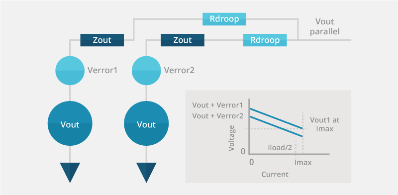
A second method to improve load sharing characteristics between multiple voltage sources is to increase the output voltage droop of each power supply such that the voltage droop at full load is significantly larger than the no-load voltage mismatch between the units. This method has the potential disadvantage that the voltage regulation of the system is degraded do to the intentional voltage droop with load current (load regulation).
Some power supplies have the ability to internally adjust the output voltage droop. This typically is performed by adjusting the internal reference voltage based upon the load current.
External resistors can be used to increase the voltage droop of a power supply if internal droop adjustment is not available and the resultant degrading in load regulation is acceptable. The droop resistors are placed in series with the outputs of the power supplies and thus the output current flows through the resistors and causes power dissipation. The voltage droop in the resistors degrades the voltage regulation and the power dissipated in the resistors degrades the power conversion efficiency of the system. The external droop resistors can be the conductors between the power supply and the load, discrete resistors placed between the supply and the load or a combination of both of these impedances.
REMOTE VOLTAGE SENSE CONNECTIONS FOR PARALLELED POWER SUPPLIES
Remote voltage sense pins should be connected directly to the Vout pins of the power module when external droop resistors are used to implement current sharing. The droop resistors are selected to intentionally degrade the load regulation of the power supplies. Conventional remote voltage sensing (connecting the sense pins close to the load) enhances the load regulation of the power supplies and thus negates the droop intentionally caused by the resistors.
PREVENTING BACK-DRIVING OF PARALLELED POWER SUPPLIES
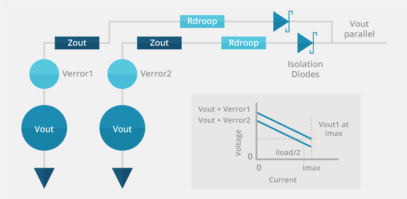
When the output terminals of multiple power supplies are connected in parallel it is possible one of the units may drive current into the output of other power supplies. In many instances this will be harmless and thus not an issue. However, with some power supplies the current driven into the output of the unit can damage the unit and thus should be prevented. One of the simplest methods to prevent current from being driven into the output of a power supply is to place an isolation diode in series with the output. The output current from the power supplies will flow through the isolation diodes and thus the set-point regulation, load regulation and power conversion efficiency will all be degraded by the use of the diodes.
SUMMARY
While it is possible to parallel almost any power supply, it should be recognized that a number of external components may be required to accomplish the task. The characteristics of the resultant power supply system may be degraded compared to what could be obtained with a single power providing the entire current for the load. Even when knowing the performance of the voltage delivery system may be reduced due to paralleling power supplies, units may be required to be operated in parallel when the current delivery characteristics of a single power supply are not adequate to provide the entire current to the load.
