- 0Sample |
- 0RFQ |
- Contact Us |
-
 ENGLISH
日本語
ENGLISH
日本語
AMT22 Arduino SPI Sample Code Tutorial
by Jason Kelly
In This Tutorial...
In this example we will use an Arduino to communicate with an AMT22 encoder. We will use the Arduino's built-in Serial Peripheral Interface (SPI) to obtain the encoder's position. We will also implement the zero command and reset command.
Code Package
DownloadHardware Required
- Arduino board
- AMT22 encoder
- AMT-06C-1-036 or any cable with the proper connector for the encoder
- AMT Programming Module
- AMT22 Datasheet
- Computer with Arduino IDE installed
AMT22 Encoders
The AMT22 is available as a 12-bit or 14-bit absolute encoder. This means that over a single revolution the encoder will have that many distinct positions. For a 12-bit encoder there are 4096 distinct positions, and for a 14-bit encoder there are 16384 positions. No matter how many times the device is rotated the encoder will always know its absolute position. Knowing the absolute position means that you will always know the exact angle of the device. With the ability to zero the encoder's position, you can define where the encoder should have its origin.
Setup
Before beginning make sure that the AMT22 encoder has the latest firmware. You can use the programming module for the AMT22 and our AMT Viewpoint software to verify the encoder firmware is up-to-date.
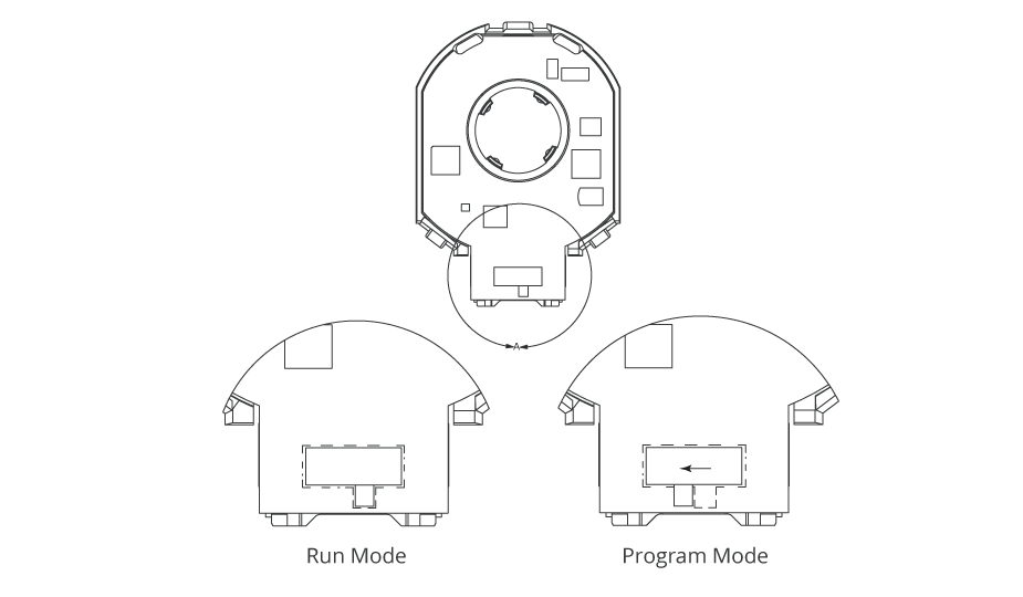
After confirming the encoder has the correct firmware, put the encoder into RUN mode by moving the switch on the back of the encoder to the proper position.
Now mount the AMT22 encoder to your motor or assembly using the AMT mounting instructions to ensure proper installation.
Circuit
The following connections are for the Arduino Uno board, however, most all Arduino boards will be compatible with this code. The connections to various Arduino boards will be different than this example, so consult Arduino documentation for additional information.
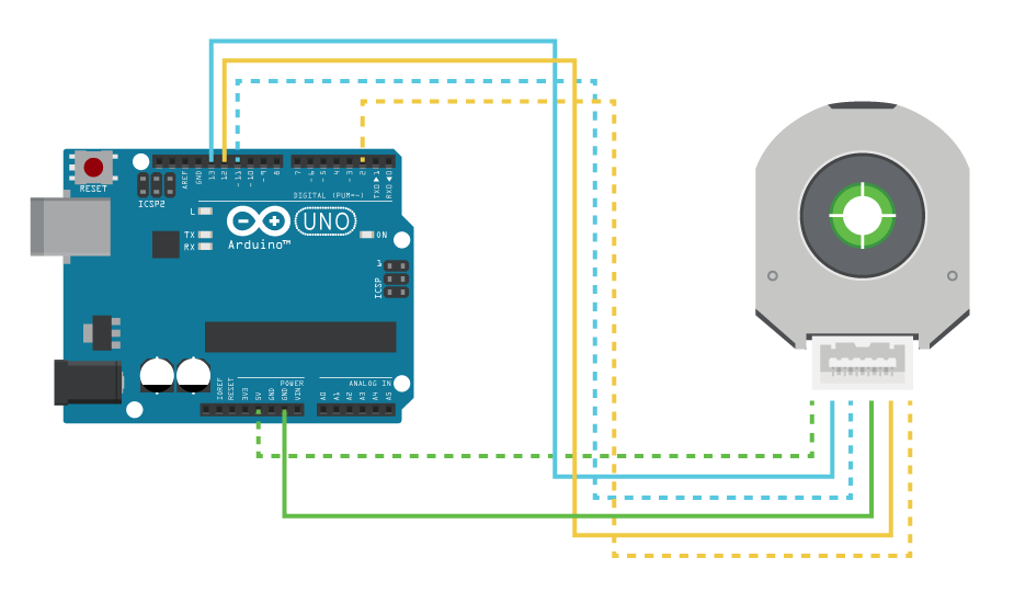
| Function | Encoder Pin Number | Arduino Uno Pin Number | AMT-036-1-036 Colors |
| +5 V | 1 | 5V | White/Green |
| SCLK | 2 | 13 | Blue/White |
| MOSI | 3 | 11 | White/Blue |
| GND | 4 | GND | Green/White |
| MISO | 5 | 12 | Orange/White |
| CHIP SELECT | 6 | 2 | White/Orange |
AMT22 Commands
The AMT22 is designed to transmit the absolute position at the very first byte, preventing the need for a command and response structure. Therefore, the host will send 0x00 as the first byte, with valid data being returned at the same time. As a result, if the host wants to send a zero or reset command, it will go on the second transmitted byte. We call these extended commands. For more information, please reference the AMT22 datasheet.
| Command | Bytes |
| Get Position | 0x00 0x00 |
| Reset Encoder | 0x00 0x60 |
| Set Zero | 0x00 0x70 |
Code Tutorial
First, since we are using the Arduino's SPI bus we need to include the SPI library.
We want to get the position from the Arduino to the computer, so we will use the built-in serial connection to the Arduino IDE. We will set the baud rate to 115200 in a define macro. We should also define the commands used by the AMT22. Because the encoder does not care about the content of the first byte, we will define it as a NOP (no-operation). Let us also define a couple of characters we can send over serial for formatting our data.
The AMT22 encoder is available as a 12-bit or 14-bit encoder, but we only want to write code once. So, we will create two defines for the resolution of the encoder that we can use with our function calls.
We also want to use defines at the top for the SPI pins. This way if the code needs to be modified for a different board, or we want to change which pins we use, it can easily be done here in one place. Moving all the numbers to the top also makes the code easier to read. It is not necessary to define the main pins for SPI communication, but it is helpful to do as a reference.
/* Include the SPI library for the arduino boards */
#include

/* Serial rates for UART */
#define BAUDRATE        115200

/* SPI commands */
#define AMT22_NOP       0x00
#define AMT22_RESET     0x60
#define AMT22_ZERO      0x70

/* Define special ascii characters */
#define NEWLINE         0x0A
#define TAB             0x09

/* We will use these define macros so we can write code once compatible with 12 or 14 bit encoders */
#define RES12           12
#define RES14           14

/* SPI pins */
#define ENC_0            2
#define ENC_1            3
#define SPI_MOSI        11
#define SPI_MISO        12
#define SPI_SCLK        13
Now that we have finished the compiler defines we can move on to executable code. Normally in C the executable code all starts in the main() function but for Arduino it is separated into two separate functions. The first one is called setup() where you can make all of your initializations, and a second one called loop() which once entered, repeats continuously.
In the setup() function we will initialize all of our SPI pins and set up our serial interfaces.
Using the Arduino function pinMode() we will set the 4 SPI pins to the proper direction. It is not necessary to set the direction of the main SPI pins (except chip select) since the SPI interface will do that for us. However, it does not hurt to do so, and can prevent issues in the event that the code is transferred to another device with different libraries or processors.
We also need to initialize the serial port so we can get data back to the host computer. We will do that by feeding the Serial.begin() function to our defined BAUDRATE.
Before initializing SPI, we should also make sure the chip select line is in the proper state. And lastly, to use the SPI bus with the AMT22 we need to select a clock rate. For prototyping we will use 500 kHz, but the encoder works up to 2 MHz. We will do this by using the SPI clock divider. The UNO has a clock rate of 16 MHz, so by using the SPI_CLOCK_DIV32 value we get a clock rate of 500 kHz. Please reference Arduino documentation for more information.
Once all that is configured it is ok to begin the SPI bus.
void setup()
{
  //Set the modes for the SPI IO
  pinMode(SPI_SCLK, OUTPUT);
  pinMode(SPI_MOSI, OUTPUT);
  pinMode(SPI_MISO, INPUT);
  pinMode(ENC_0, OUTPUT);
  pinMode(ENC_1, OUTPUT);

  //Initialize the UART serial connection for debugging
  Serial.begin(BAUDRATE);

  //Get the CS line high which is the default inactive state
  digitalWrite(ENC_0, HIGH);
  digitalWrite(ENC_1, HIGH);

  //set the clockrate. Uno clock rate is 16Mhz, divider of 32 gives 500 kHz.
  //500 kHz is a good speed for our test environment
  //SPI.setClockDivider(SPI_CLOCK_DIV2);   // 8 MHz
  //SPI.setClockDivider(SPI_CLOCK_DIV4);   // 4 MHz
  //SPI.setClockDivider(SPI_CLOCK_DIV8);   // 2 MHz
  //SPI.setClockDivider(SPI_CLOCK_DIV16);  // 1 MHz
  SPI.setClockDivider(SPI_CLOCK_DIV32);    // 500 kHz
  //SPI.setClockDivider(SPI_CLOCK_DIV64);  // 250 kHz
  //SPI.setClockDivider(SPI_CLOCK_DIV128); // 125 kHz

  //start SPI bus
  SPI.begin();
}
If the only communication we were going to do with the AMT22 encoder was reading the position, we could write a function to handle that entirely. However, to get more use out of our code we will first write a command to handle reading and writing to the SPI bus with the AMT22 encoder, and then we will write a separate function specifically to get the position, zero the encoder, or reset the encoder.
SPI calls are done with the SPI library of the Arduino, but the chip select of devices is controlled by us in code using the digital IO pins. We could use the digitalWrite() function to do this, but our preference is to create a helper function that makes our code more decipherable during troubleshooting.
Creating a function called setCSLine() makes it clearer what the purpose of the call is for, but using digitalWrite() alone is also acceptable.
/*
 * This function sets the state of the SPI line. It isn't necessary but makes the code more readable than having digitalWrite everywhere
 * This function takes the pin number of the desired device as an input
 */
void setCSLine (uint8_t encoder, uint8_t csLine)
{
  digitalWrite(encoder, csLine);
}
We now need a function to communicate with the AMT22 encoder. We want this function to be useful for any different byte you want to send to the encoder so we will take two parameters. The first is the 8-bit byte we are sending the encoder, while the second parameter will tell the function if it should release the chip select line or not. Because the AMT22 has a two-byte command structure, we do not want to release the chip select (CS) line after the first byte, but we do after the second. Therefore, the calling code will use the spiWriteRead() function twice, releasing the CS line only on the second call.
We will create a uint8_t to hold the incoming data. Next, we can go ahead and set the chip select low to initialize SPI. The AMT22 has a minimum time from when you pull CS low to when you can start clocking data, listed in the datasheet as 2.5 microseconds. This time is likely observed inherently in the time it takes the Arduino to execute the IO change and start SPI transfer, but we will implement it in code anyways to be safe.
Now we can call SPI.transfer(sendByte) with the returned value being the data from the SPI bus. We will call setCSLine() with the given parameter releaseLine; there is no need to check the value of releaseLine because the value matches the desired state of the chip select line. Finally, the function will return the data variable.
/*
 * This function does the SPI transfer. sendByte is the byte to transmit.
 * Use releaseLine to let the spiWriteRead function know if it should release
 * the chip select line after transfer.
 * This function takes the pin number of the desired device as an input
 * The received data is returned.
 */
uint8_t spiWriteRead(uint8_t sendByte, uint8_t encoder, uint8_t releaseLine)
{
  //holder for the received over SPI
  uint8_t data;

  //set cs low, cs may already be low but there's no issue calling it again except for extra time
  setCSLine(encoder ,LOW);

  //There is a minimum time requirement after CS goes low before data can be clocked out of the encoder.
  //We will implement that time delay here, however the arduino is not the fastest device so the delay
  //is likely inherantly there already
  delayMicroseconds(3);

  //send the command
  data = SPI.transfer(sendByte);
  delayMicroseconds(3); //There is also a minimum time after clocking that CS should remain asserted before we release it
  setCSLine(encoder, releaseLine); //if releaseLine is high set it high else it stays low

  return data;
}
Now it is time for the fun part. With our helper functions completed, it is time to create a function to obtain position from the AMT22 encoder.
The AMT22 expects two bytes of 0x00 to be sent and it returns data immediately with those two bytes. Because of this fast response there are some minimum timing requirements that should be observed, please see the datasheet for more information.
It does not matter if the encoder has a resolution of 12-bits or 14-bits, it will always respond with two full bytes totaling 16 bits. The upper two bits are check-bits that allow us to confirm the data’s integrity. If the encoder is a 12-bit version, the bottom two bits will both be 0. For this data to be useful it must be shifted right 2 bits (or divided by 4).
Because the AMT22 is available in two resolution options, we will write our code to work with either. The function we are writing called getPosition() will have an input parameter that tells it which resolution to format the data for.
Starting off we need to create some variables that we can use for holding the 16-bit response from the encoder, and then we will create an array to hold each bit individually so we can calculate our checksum.
Next, we want to call our spiWriteRead() function, sending the AMT22_NOP command. We will leave CS low. The high byte comes first, so in a single line of code we will call the function, shift it left 8 bits to get that first byte (8 bits) into the top half of the uint16_t variable, and assign it to currentPosition. We need to put a small delay to meet the AMT22 timing requirements, but then we can send the follow-up command. Again doing this in a single line we are calling the spiWriteRead() command, sending it AMT22_NOP, telling it to release the CS line, and then OR'ing the value with the currentPosition variable; this is basically the same as simply adding the values together.
/*
 * This function gets the absolute position from the AMT22 encoder using the SPI bus. The AMT22 position includes 2 checkbits to use
 * for position verification. Both 12-bit and 14-bit encoders transfer position via two bytes, giving 16-bits regardless of resolution.
 * For 12-bit encoders the position is left-shifted two bits, leaving the right two bits as zeros. This gives the impression that the encoder
 * is actually sending 14-bits, when it is actually sending 12-bit values, where every number is multiplied by 4.
 * This function takes the pin number of the desired device as an input
 * This funciton expects res12 or res14 to properly format position responses.
 * Error values are returned as 0xFFFF
 */
uint16_t getPositionSPI(uint8_t encoder, uint8_t resolution)
{
  uint16_t currentPosition;       //16-bit response from encoder
  bool binaryArray[16];           //after receiving the position we will populate this array and use it for calculating the checksum

  //get first byte which is the high byte, shift it 8 bits. don't release line for the first byte
  currentPosition = spiWriteRead(AMT22_NOP, encoder, false) << 8;

  //this is the time required between bytes as specified in the datasheet.
  //We will implement that time delay here, however the arduino is not the fastest device so the delay
  //is likely inherantly there already
  delayMicroseconds(3);

  //OR the low byte with the currentPosition variable. release line after second byte
  currentPosition |= spiWriteRead(AMT22_NOP, encoder, true);
Now that we have completed the SPI transfer we need to validate the data. There are many ways to do this checksum calculation, some probably faster than this, but here we will do it in a way that makes it very simple to understand.
First, we need to put the 16-bits we received into our boolean array. We will do this by using a for loop to run through all 16 bits, placing each one into the array. As we increment i we will shift currentPosition to the right that many places to get the bit we care about into the 1’s spot, while we AND that with 0x01 to only get that bit; then we assign it to that position in the binaryArray[].
  //run through the 16 bits of position and put each bit into a slot in the array so we can do the checksum calculation
  for(int i = 0; i < 16; i++) binaryArray[i] = (0x01) & (currentPosition >> (i));
Using the equation from the datasheet we can build our code to verify the expected value against what was received. The check-bits are odd parity over the odd and even bits in the position response. So, we will check for parity against all the odd bits (bit 1, 3, 5, 7, 9, 11, 13) and parity against even (0, 2, 4, 6, 8, 10, 12, 14).
If the check-bits are correct, then we want to update the currentPosition variable, stripping out the upper two bits. We AND our currentPosition variable with 0x3FFF (0b0011111111111111) to make sure we retain all 14 lower bits. If the check-bits do not match the position, we will use the error value 0xFFFF to let the caller know.
We have one final step. We need to check the parameter resolution to determine if the encoder has 12-bit or 14-bit resolution. If the resolution is 12-bits, and there was not a bad response, then simply shift the bits to the right 2 (divide by 4) and assign that to currentPosition. Now return the value.
  //using the equation on the datasheet we can calculate the checksums and then make sure they match what the encoder sent
  if ((binaryArray[15] == !(binaryArray[13] ^ binaryArray[11] ^ binaryArray[9] ^ binaryArray[7] ^ binaryArray[5] ^ binaryArray[3] ^ binaryArray[1]))
          && (binaryArray[14] == !(binaryArray[12] ^ binaryArray[10] ^ binaryArray[8] ^ binaryArray[6] ^ binaryArray[4] ^ binaryArray[2] ^ binaryArray[0])))
    {
      //we got back a good position, so just mask away the checkbits
      currentPosition &= 0x3FFF;
    }
  else
  {
    currentPosition = 0xFFFF; //bad position
  }

  //If the resolution is 12-bits, and wasn't 0xFFFF, then shift position, otherwise do nothing
  if ((resolution == RES12) && (currentPosition != 0xFFFF)) currentPosition = currentPosition >> 2;

  return currentPosition;
}
With the more complicated command completed, we can build out our extended commands.
Setting the zero position of the encoder means sending the two-byte command sequence. First, send the AMT22_NOP command, wait the minimum amount of time required by the AMT22, and send the AMT22_ZERO command, making sure to release the chip select line. Once the command is received the encoder will complete a reset. To make sure we are not talking to the encoder during this power on time we will implement a delay of 250 mS to be safe.
/*
 * The AMT22 bus allows for extended commands. The first byte is 0x00 like a normal position transfer, but the
 * second byte is the command.
 * This function takes the pin number of the desired device as an input
 */
void setZeroSPI(uint8_t encoder)
{
  spiWriteRead(AMT22_NOP, encoder, false);

  //this is the time required between bytes as specified in the datasheet.
  //We will implement that time delay here, however the arduino is not the fastest device so the delay
  //is likely inherantly there already
  delayMicroseconds(3);

  spiWriteRead(AMT22_ZERO, encoder, true);
  delay(250); //250 second delay to allow the encoder to reset
}
Very similarly the reset command is also two bytes, and since a reset occurs the power on time should be observed here as well.
/*
 * The AMT22 bus allows for extended commands. The first byte is 0x00 like a normal position transfer, but the
 * second byte is the command.
 * This function takes the pin number of the desired device as an input
 */
void resetAMT22(uint8_t encoder)
{
  spiWriteRead(AMT22_NOP, encoder, false);

  //this is the time required between bytes as specified in the datasheet.
  //We will implement that time delay here, however the arduino is not the fastest device so the delay
  //is likely inherantly there already
  delayMicroseconds(3);

  spiWriteRead(AMT22_RESET, encoder, true);

  delay(250); //250 second delay to allow the encoder to start back up
}
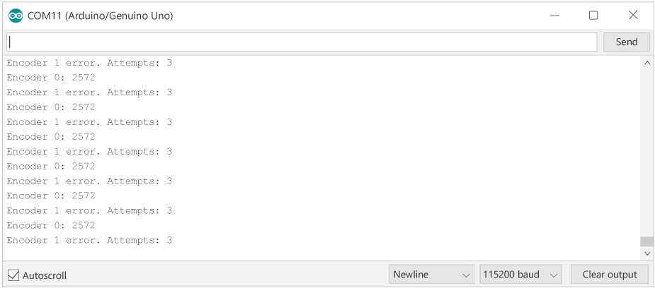
With all the necessary functions created, we can implement these commands and talk to the encoder. Back in our main loop we should create two variables, the first is a uint16_t to hold the encoder’s position, and the second a counter to keep track of how many attempts it took to get a good position value.
We can have our code set the zero position of the encoder first if we want, however, in normal applications you would only set the zero position once when configuring the device for use in the system.
After that we will create an infinite loop where we read the encoder’s position, send the value to the computer, and repeat. Every time we hit the top of the loop we will zero out the attempts counter. Start by getting the encoder’s position with our getPositionSPI() function. Now we can check and see if that value is good, and if not, try again. Remember that a bad value is returned as 0xFFFF so we will create a simple while loop to try again. If the position is 0xFFFF and our attempts counter has not yet hit 3 tries, keep trying.
After we have passed the while loop, either with success or failure, we can check on the position value again and let the host computer know what happened.
If the position is bad, let the user know there was an error, and how many times we tried. If the position is good, simply report the position in the decimal format.
We can delay here for a half second before repeating the loop.
void loop()
{
  //create a 16 bit variable to hold the encoders position
  uint16_t encoderPosition;
  //let's also create a variable where we can count how many times we've tried to obtain the position in case there are errors
  uint8_t attempts;


  //if you want to set the zero position before beggining uncomment the following function call
  //setZeroSPI(ENC_0);
  //setZeroSPI(ENC_1);

  //once we enter this loop we will run forever
  while(1)
  {
    //set attemps counter at 0 so we can try again if we get bad position
    attempts = 0;

    //this function gets the encoder position and returns it as a uint16_t
    //send the function either res12 or res14 for your encoders resolution
    encoderPosition = getPositionSPI(ENC_0, RES14);

    //if the position returned was 0xFFFF we know that there was an error calculating the checksum
    //make 3 attempts for position. we will pre-increment attempts because we'll use the number later and want an accurate count
    while (encoderPosition == 0xFFFF && ++attempts < 3)
    {
      encoderPosition = getPositionSPI(ENC_0, RES14); //try again
    }

    if (encoderPosition == 0xFFFF) //position is bad, let the user know how many times we tried
    {
      Serial.print("Encoder 0 error. Attempts: ");
      Serial.print(attempts, DEC); //print out the number in decimal format. attempts - 1 is used since we post incremented the loop
      Serial.write(NEWLINE);
    }
    else //position was good, print to serial stream
    {

      Serial.print("Encoder 0: ");
      Serial.print(encoderPosition, DEC); //print the position in decimal format
      Serial.write(NEWLINE);
    }

    //////////again for second encoder//////////////////////////////

    //set attemps counter at 0 so we can try again if we get bad position
    attempts = 0;

    //this function gets the encoder position and returns it as a uint16_t
    //send the function either res12 or res14 for your encoders resolution
    encoderPosition = getPositionSPI(ENC_1, RES14);

    //if the position returned was 0xFFFF we know that there was an error calculating the checksum
    //make 3 attempts for position. we will pre-increment attempts because we'll use the number later and want an accurate count
    while (encoderPosition == 0xFFFF && ++attempts < 3)
    {
      encoderPosition = getPositionSPI(ENC_1, RES14); //try again
    }

    if (encoderPosition == 0xFFFF) //position is bad, let the user know how many times we tried
    {
      Serial.print("Encoder 1 error. Attempts: ");
      Serial.print(attempts, DEC); //print out the number in decimal format. attempts - 1 is used since we post incremented the loop
      Serial.write(NEWLINE);
    }
    else //position was good, print to serial stream
    {

      Serial.print("Encoder 1: ");
      Serial.print(encoderPosition, DEC); //print the position in decimal format
      Serial.write(NEWLINE);
    }

    //For the purpose of this demo we don't need the position returned that quickly so let's wait a half second between reads
    //delay() is in milliseconds
    delay(500);
  }
}
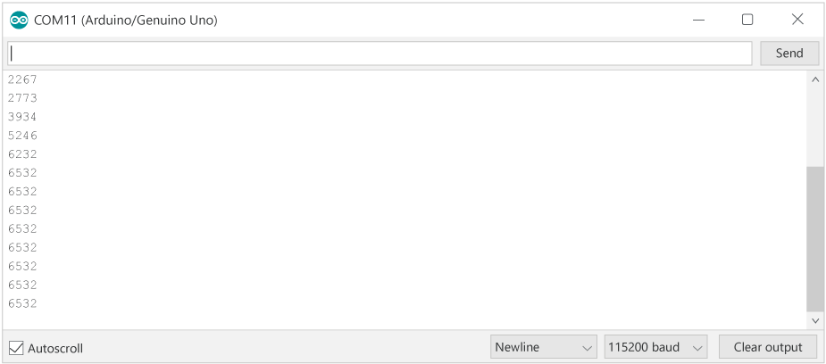
Now that our code has been created, we can load it onto the Arduino and get talking to an encoder. Open the serial monitor, make sure the data rate is set to 115200, and see the encoder work.
Now that we have learned how to talk to the AMT22 encoder, there are a couple very useful changes we can make. The benefit of an SPI device is that you can talk to multiple encoders on the same bus. To do this we will need to allocate another digital IO pin, and modify our functions to accept the pin number of the device we want to talk to.
/* SPI pins */
#define ENC_0            2
#define ENC_1            3
#define SPI_MOSI        11
#define SPI_MISO        12
#define SPI_SCLK        13
//Set the modes for the SPI IO
pinMode(SPI_SCLK, OUTPUT);
pinMode(SPI_MOSI, OUTPUT);
pinMode(SPI_MISO, INPUT);
pinMode(ENC_0, OUTPUT);
pinMode(ENC_1, OUTPUT);
After data is transferred there is a minimum time before the chip select line can be released. This is specified in the datasheet as 3 microseconds. For slower data rates this is observed naturally, but we will implement it anyways.
To see how the SPI functions were modified to accept the encoder number, download the package below!