Why is Power Factor Important When Measuring Efficiency?
May 22, 2018 by Ron Stull -
8 Minute Read
Last updated October 24, 2023
The Basics of Power Factor and Efficiency
Engineers using external power supplies (EPS) are no stranger to efficiency measurements. However, as their applications typically run on dc power, common mistakes can be made when measuring the power on the ac side of the power supply. These common pitfalls include incorrectly measuring or completely omitting power factor when calculating the power input to the supply, which results in incorrect efficiency measurements. In this blog post, we will review the basics of power factor and efficiency, then provide guidance on how to incorporate power factor when measuring ac-dc power supply efficiency.
Power Factor and Efficiency, a Review
Efficiency (η) is the ratio of output power to input power:

In the context of an External Power Supply (EPS) dealing with direct current, the output power is calculated by simply multiplying the output voltage by the output current by quickly providing the numerator to equation.
Calculating Output Power
Calculating the output power of an EPS, which is dc, is simply the output voltage multiplied by the output current:

Equation 2 calculates the direct current (dc) output power (P_dc) of an Electric Power Supply (EPS) by multiplying the output voltage (V_dc) by the output current (I_dc), resulting in the power measured in watts (W).
Understanding Power Factor
A common mistake is to apply this same calculation to obtain the input power. This presents a problem because the volt-ampere product in ac circuits does not always equal the real power, and in fact, in the case of external adapters, the volt-ampere product will never equal the real power. In ac circuits, the volt-ampere product is equal to the apparent power (S), which is related to the real pow-er through a term called Power Factor (PF):

Equation 3 computes the apparent power (S) in volt-amperes (VA) by multiplying the root mean square (rms) voltage (Vrms) with the rms current (Irms).
Defining Power Factor
By definition, power factor is the ratio of real power to apparent power, where apparent power is the product of the rms voltage and rms current. Only when the power factor equals 1 does the volt-ampere product equal the real power:

Different Types of Power Factor
If power factor is considered when calculating the efficiency, it must be calculated correctly. Many engineers have to rewind all the way back to their early engineering classes to remember what power factor is and how to measure it. However, in school they of-ten focus on a linear case where both the voltage and current are pure sinusoids of equal frequency. In this case the power factor is simply the cosine of the phase difference between the voltage and current and is more accurately known as the displacement power factor:

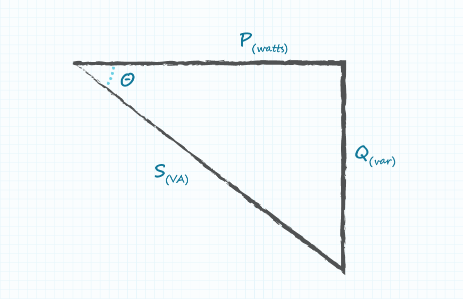
Many engineers are familiar with the power triangle, shown in Figure 1, which visually represents the relationship of Equation 5. By definition, the cosine of θ is equal to the ratio of the adjacent side to the hypotenuse. In the power triangle this equals the ratio of real power to apparent power, which matches our definition in Equation 4. On the other hand, when it comes to non-linear systems, of which ac-dc power supplies are one example, this does not present the whole picture.
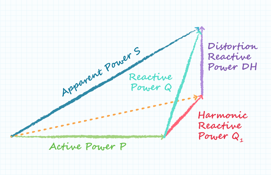
The Role of Distortion Power Factor
What is missing is the distortion power factor, which adds a third dimension to the power triangle as shown in Figure 2. This point is critical because in power supplies the distortion factor is the major contributor to reducing power factor since the displacement factor tends to be close to unity.
Total Harmonic Distortion
Fourier analysis shows that this non-linear current waveform can be broken down into a series of harmonic components of various magnitudes. These harmonics decrease the power factor, but are not accounted for in Equation 5. To calculate the distortion power factor, Total Harmonic Distortion (THD) is introduced. THD takes into account the current associated with each harmonic as high-lighted in the following equation:

Calculating the Distortion Power Factor
When the THD is equal to 0, the distortion power factor is equal to 1, which would be the case for a linear system:

The True Power Factor
The power factor picture is completed by multiplying the displacement power factor and distortion power factor, which results in the True Power Factor:

Figure 3 shows the input current and voltage waveforms of a typical power supply. When compared to the sinusoidal voltage, the non-linear nature of the current can be clearly seen.
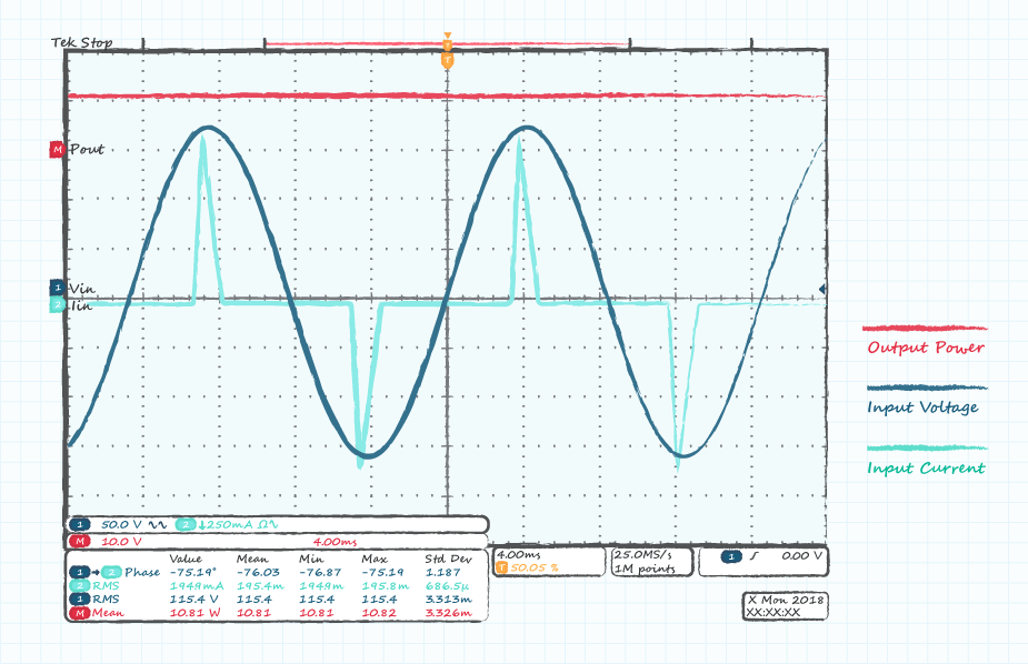
This is caused by the combination of a bridge rectifier and bulk-capacitor that create a high-voltage dc bus inside the supply. The rectifier is forward biased and only conducts current when the input voltage exceeds the voltage on the bulk-capacitor.
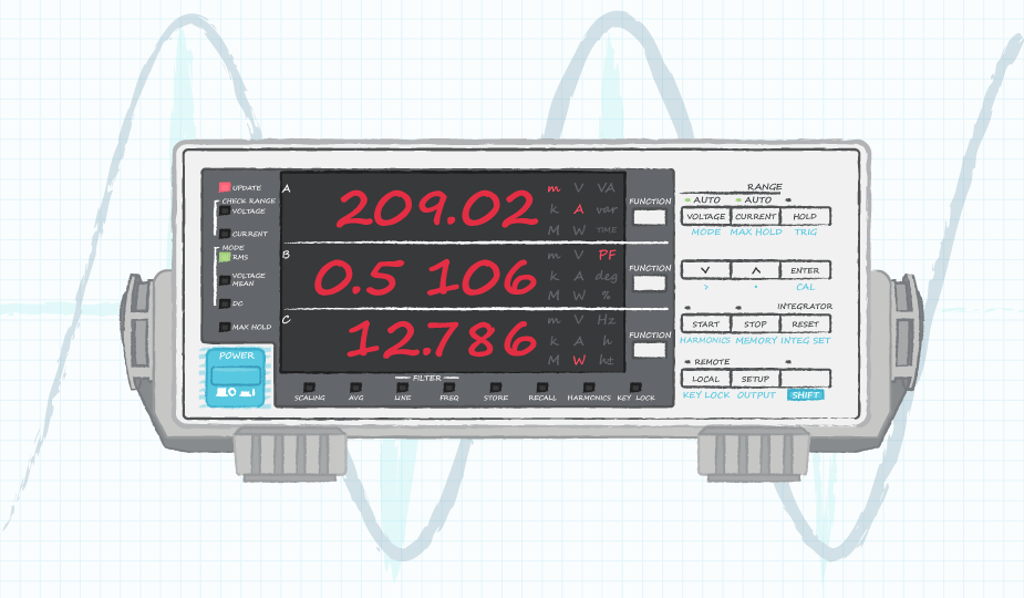
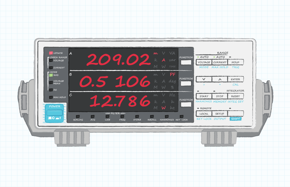
Measuring Power Factor
The best way to measure power factor is to use a power meter like the one shown in Figure 4 below. These devices will output the real power directly, so power factor does not need to be considered when calculating efficiency. In addition to the real power, these meters can measure power factor, THD, the current for each harmonic, and more. While low power external adapters do not have de-fined power factor or harmonic limits, higher power supplies do have specific regulatory limits on the harmonic content and power factor. Standards, such as EN 61000-3-2 specify limits on harmonic current up to and including the 39th harmonic, for certain power levels. When measuring the harmonic current of a power supply, a power meter is essential.
Power Factor in Power Supplies
You may think that the impact of omitting the power factor will result in only a slight error and/or that the power factor of an external adapter cannot be that bad. In fact, without power factor correction, the power factor of an external adapter could easily be as low as 0.5 at a rated load. An adapter with a power factor of 0.5 will have an apparent power twice that of the real power, thus leading to incorrect results. Even if the power supply had a real efficiency of 100%, this measurement would only show 50%.
In addition to the general inclusion of power factor in efficiency calculations, it is important to note that the power factor is line and load dependent. Efficiency requirements, such as DoE Level VI, require the efficiency to be measured at several points (25%, 50%, 75%, and 100% load) at both high and low line voltages. If power factor is used in the calculation of real power, then it must be re-measured for each of these conditions.
Real World Example: The Impact of Power Factor
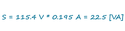
As a real-world example, take Figures 3 and 4, which were obtained from a 20 W external power supply operating at 10.8 W. With measurements obtained from the scope in Figure 3, we end up with a volt-ampere product of 22.5 VA. If we were to forget to include power factor, then using this number we would gather an efficiency figure of 48%:

Utilizing a power meter, like that shown in Figure 4, we see that the real input power is actually only 12.8 W, and using this value we end up with an efficiency of 84%, which is nearly twice what we obtained without factoring in the power factor:

Now if power factor was considered, but an oscilloscope and Equation 5 were used to calculate it (distortion factor omitted), a few problems present themselves. First, as shown in Figure 3, scopes can have trouble automatically calculating the phase difference. The scope used in Figure 3 calculated a phase angle of 72 degrees, which appears to be incorrect to the naked eye. When using scope cursors to manually measure the phase angle, we notice that we are attempting to measure the offset of two differently shaped waveforms and that the current waveform pulse is asymmetric.
So the question arises: where do we put the cursor, at the peak or at the center of the pulse? In either case the value ends up being a few degrees at most. Were we to use Equation 5 to calculate the displacement power factor with an angle of 5°, we end up with a value of 0.996. If we multiply our result of 22.5 VA gathered above by our calculated power factor, we find the result is nearly unchanged at 22.4 VA. This should confirm our earlier assertion that the displacement factor is close to unity and the distortion power factor is the dominant term in Equation 8. We can therefore see that the scope method is of no use to us and the only method that produced correct results was the use of a power meter.
Power Meters for Accurate Efficiency Testing
Decades of increasing regulation have made efficiency testing one of the most important factors in selecting and qualifying power supplies. Lack of experience in dealing with ac circuits can lead test engineers to omit or to incorrectly calculate the power factor, resulting in incorrect efficiency numbers. When testing external adapters, or any ac-dc power supply, the best method for calculating the real power input is through the use of a power meter. These devices not only measure real power directly but can measure the current associated with the individual harmonics and provide a complete picture of the power supply input.
Fundamentals , Testing & Failure Analysis
You May Also Like


Have comments regarding this post or topics that you would like to see us cover in the future?
Send us an email at powerblog@cui.com


Ron Stull
Ron Stull has gathered a range of knowledge and experience in the areas of analog and digital power as well as ac-dc and dc-dc power conversion since joining CUI in 2009. He has played a key role on CUI’s Engineering team with responsibilities including application support, test and validation, and design. Outside of power engineering Ron can be found playing guitar, running, and touring the outdoors with his wife, where their goal is to visit all of the U.S. National Parks.