Understanding Power Supply Output Capacitance Limits
June 20, 2023 by Bruce Rose - 5 Minute Read
In previous blog posts we have described the internal components of switching power supplies (“How Switch Mode Power Supplies Work, Block by Block”) and the characteristics of output filter capacitors used for filtering (“Selecting Output Capacitors for Power Supply Applications”). However, these articles did not explain why many power supplies have a maximum specified value for the capacitance that the user is allowed to place on the output of a power supply. In this article we will review the electrical principles of capacitors so we can understand why it may not be that “if some is good, then more must be better” when placing capacitance on the output of a power supply.
What is the Purpose of Output Capacitance?
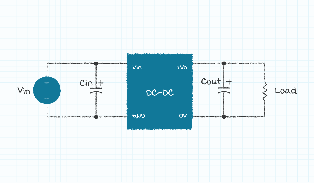
As is the case with most design tasks, there are multiple constraints affecting the capacitance used on the output of a power supply. One purpose of capacitors on the output of a power supply is to attenuate undesired electrical noise as the power is delivered to the external load. Another purpose of capacitors on the output of a power supply is to minimize the change in output voltage due to the occurrence of load current transients.
If attenuating noise and minimizing output voltage changes are the only considerations involved in selecting the capacitance to be placed on the output of a power supply, then more capacitance may be better. Unfortunately, other characteristics of power supplies can be affected in a negative manner when the capacitance placed on the output of the supplies is increased.
Effects of Increased Output Capacitance
One of the characteristics of power supplies that is affected by increased capacitance on the output of the supply is the output overcurrent protection (OCP) function. The OCP function is included in power supplies to protect the supplies from damage if the load current is too great. Excessively large output currents can be required from power supplies when the output voltage rises during start-up if the capacitance on the output is great enough.
The interaction of the capacitance on the output of a supply with the start-up voltage ramp can best be understood by a review of the basic electrical principles of capacitors. A fundamental description regarding the characteristics of a capacitor is shown in equation 1.

The current (I) into (or out of) a capacitor is equal to the value of the capacitance (C) times the change in voltage across the capacitor (dV) divided by the change in time (dt) during which the change in voltage occurs. It can be seen from the equation that the current associated with the capacitor increases as the value of the capacitance increases, the change in voltage increases, and the time associated with the change in voltage decreases. Recall also that power supplies employ feedback in the output voltage control topology to produce a precision output voltage. It then becomes apparent that when an output load current transient occurs there will be a time delay in the output voltage response due to the finite bandwidth of the control loop.
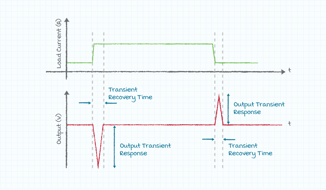
The output voltage of the supply can be stabilized during the time before the control loop can respond by using capacitance to compensate for the transient load current during the delay time. A larger value of capacitance provides better stabilization of the output voltage caused by the output load current transient. Also relating to the output capacitance, the output voltage change during the start-up of a power supply also appears as a dV/dt event across the terminals of the capacitor and thus causes a current to flow into the capacitor. The current required to charge the capacitance on the output of a power supply during output voltage start-up must come from the power supply.
Example Application
A simple example circuit can be analyzed to provide a sense of the levels of capacitance, voltage, and current associated with a power supply. We will analyze a switching power supply with the following characteristics and design goals:
- Switching frequency: 100 kHz
- Bandwidth of power supply control loop: 10 kHz
- Power supply output voltage: 12 V
- Power supply output current: 500 mA
- Voltage transient for 25~75% load current step: 120 mV
- Start-up rise time: 10 ms
If we assume a supply operating at a switching frequency of 100 kHz, then it is reasonable to assume a closed loop bandwidth of 10 kHz for the supply feedback network (loop bandwidth set to 1/10 of the switching frequency). A single pole network with a 10 kHz bandwidth will have a 10% to 90% rise time of about 35 µs (Tr = 0.35/BW). If we are willing to have a of a 120 mV transient in the output voltage of our power supply before the feedback network takes affect then we will require about 73 µF of capacitance on the output of the supply for a 250 mA transient. During start-up this supply will be required to provide only 90 mA of current to charge the output capacitor.
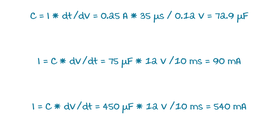
This level of output current will not be an issue. However, if the user decides to place 450 µF of output capacitance to have only 20 mV of voltage deviation during the load current transient, then the current required to charge the output capacitance will be and the supply may enter OCP mode during start-up.
Overcurrent Faults During Startup
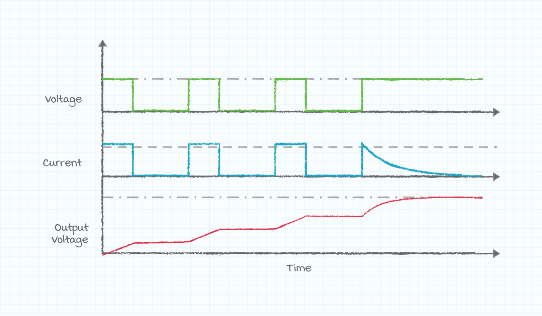
Most switching supplies employ hiccup mode for the OCP implementation scheme. Hiccup mode is employed because it is easy to incorporate into the voltage controller IC and it reduces stress on the power supply components during output over current events. An additional benefit of employing hiccup mode for OCP is the size, weight, and cost of power supplies can be reduced. As was mentioned previously, the power supply may enter OCP mode if the load current required to charge the capacitance on the output of the supply during start-up is greater than the rated output current of the supply.
It is possible that if the power supply enters OCP mode during start-up that the power supply output voltage rises in a stair-step manner and properly reaches the desired output voltage (see figure 3). It is also possible when in OCP mode that due to leakage or other current draw during the start-up phase the output capacitance is never able to achieve the desired value. Operating in OCP mode is an abnormal condition and thus power supply designers often specify a maximum load capacitance to be placed on the output of the power supply so that the supply is not intentionally operated in OCP mode. Please read this web article (“Fundamentals of Power Supply Over Current Protection”) for a more detailed description of OCP in power supplies.
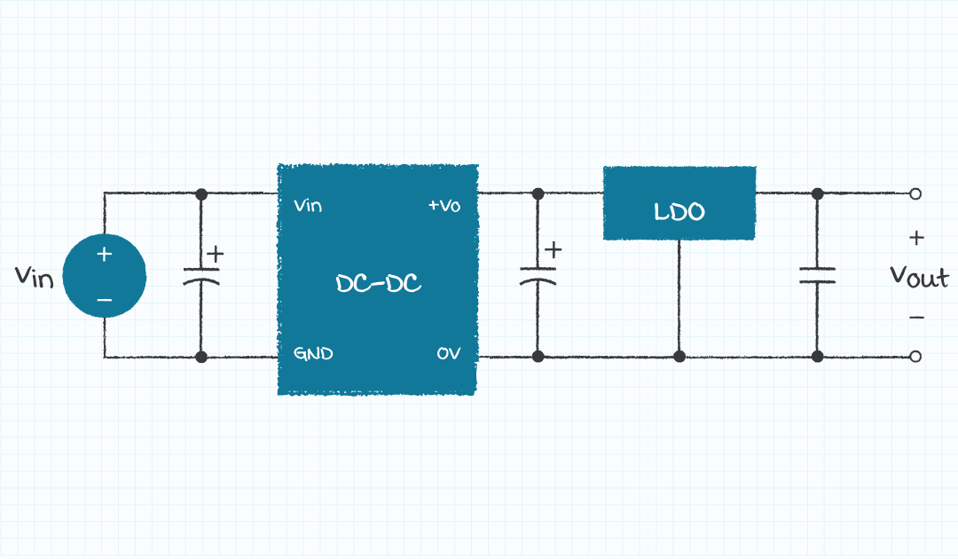
Improving Transient Response with External Linear Regulator
In some applications the product designer may be able to place a low drop-out linear regulator (LDO) between the output of the switching power supply and the load to reduce output voltage transients due to output load current transients and power supply noise. An LDO can be selected with a higher closed loop bandwidth than the switching regulator and thus the output capacitance will not need to be as large for the same system performance.
Ask the Power Supply Experts
In this presentation, we have discussed how a design engineer might select the amount of capacitance to place on the output of a power supply and how that decision may affect the supply during start-up mode. It is the recommendation of CUI that if the user decides to design their product such that the power supply knowingly enters OCP mode during start-up that they understand the risks and verify that their product performs in an acceptable manner. The experts and engineers at CUI can help you understand the behavior and effects that excessive output capacitance may have in your application and direct you to an optimal solution.
You May Also Like
Have comments regarding this post or topics that you would like to see us cover in the future?
Send us an email at powerblog@cui.com


Bruce Rose
During his many years in the electronics industry working in design, sales, and marketing, Bruce Rose has focused on analog circuits and power delivery. His range of work experience includes organizing and chairing international workshops, publishing and presenting in more than 40 technical conferences and journals, and having been awarded seven patents. While he enjoys his time at work, Bruce further enjoys the time he is able to spend with his family hiking, biking, and canoeing as well as pursuing his passion of full scale and model aviation.